On-vehicle rotary electric machine and electric power steering system

Inactive Publication Date: 2013-10-10
HITACHI AUTOMOTIVE SYST LTD
View PDF6 Cites 11 Cited by
  • Summary
  • Abstract
  • Description
  • Claims
  • Application Information

AI Technical Summary

Benefits of technology

The invention prevents the stator core from spinning in the chassis without adding a separate part to stop it.

Problems solved by technology

However, a member dedicated for preventing rotation of the stator core is added in the structure according to JP 2011-67056 A, which becomes a factor of cost increase as well as a hindrance for downsizing the electrical motor.

Method used


Image

  • On-vehicle rotary electric machine and electric power steering system
  • On-vehicle rotary electric machine and electric power steering system
  • On-vehicle rotary electric machine and electric power steering system

Examples


second embodiment

[0060]FIGS. 10 to 15 are views illustrating a second embodiment of the present invention. FIGS. 10 and 11 are views of an engaging portion according to this embodiment. As in FIG. 10, an engaging portion 13c, which is formed in the end portion in the axial direction of the bobbin 13, is a V-shaped recess formed in a projection that is wider in a circumferential direction. On the other hand, as in FIG. 11, an engaging portion 10f engaged with an engaging portion 13c is formed in the chassis 10 in the same number as the divided cores 12a. In the inner periphery surface of the chassis 10, a recess and a projection are formed along the circumferential direction, and the recess becomes the engaging portion 10f.

[0061]FIG. 12 is a perspective view of the rotor 18 and the stator core 12 having the bobbin 13 installed therein as in FIG. 10, configured to be a 10-pole 12-slot two-parallel winding structure. Regarding the lead wire of the coil 14, the wire is led out straightly upward at the ...


PUM


Abstract

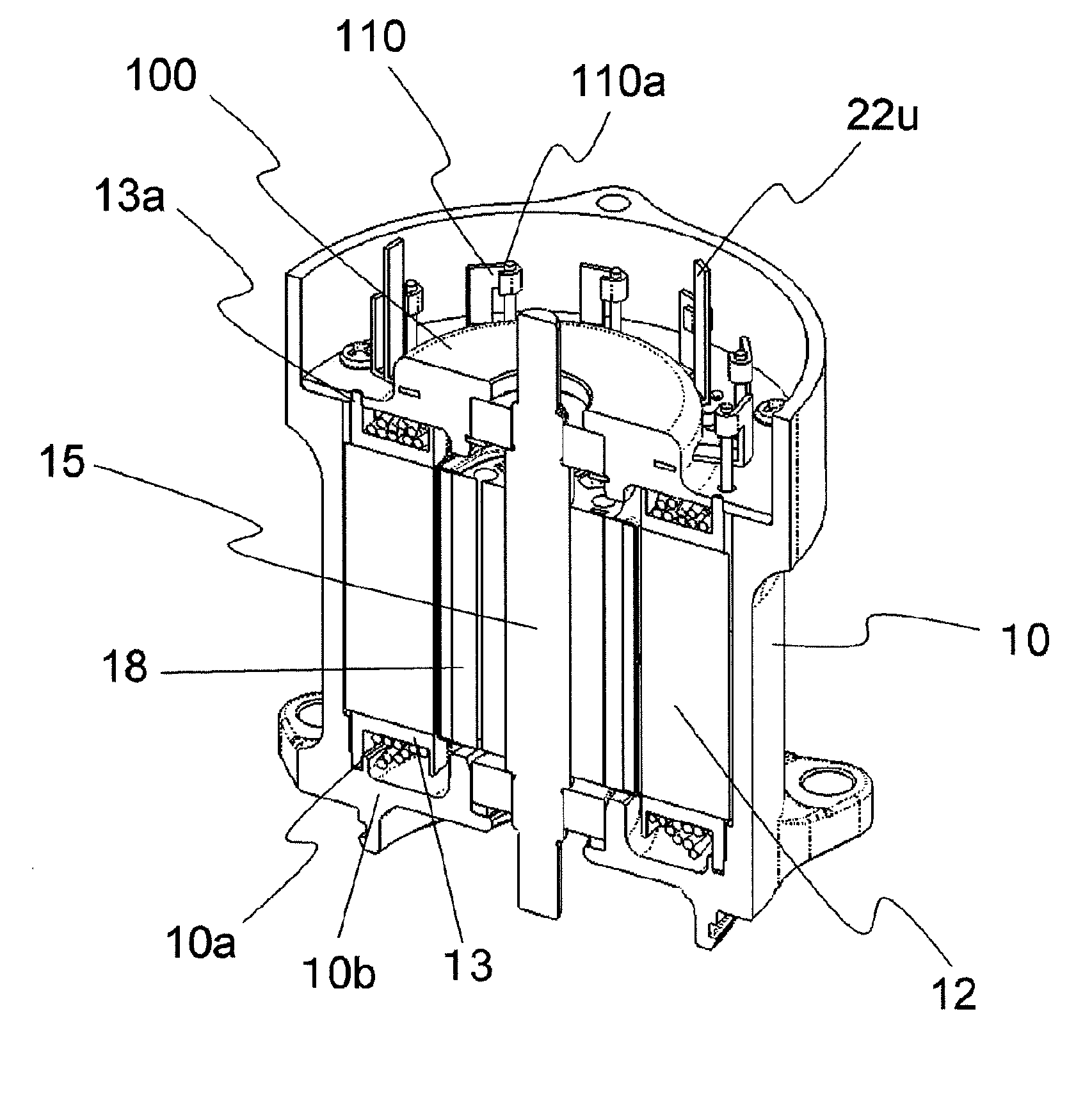
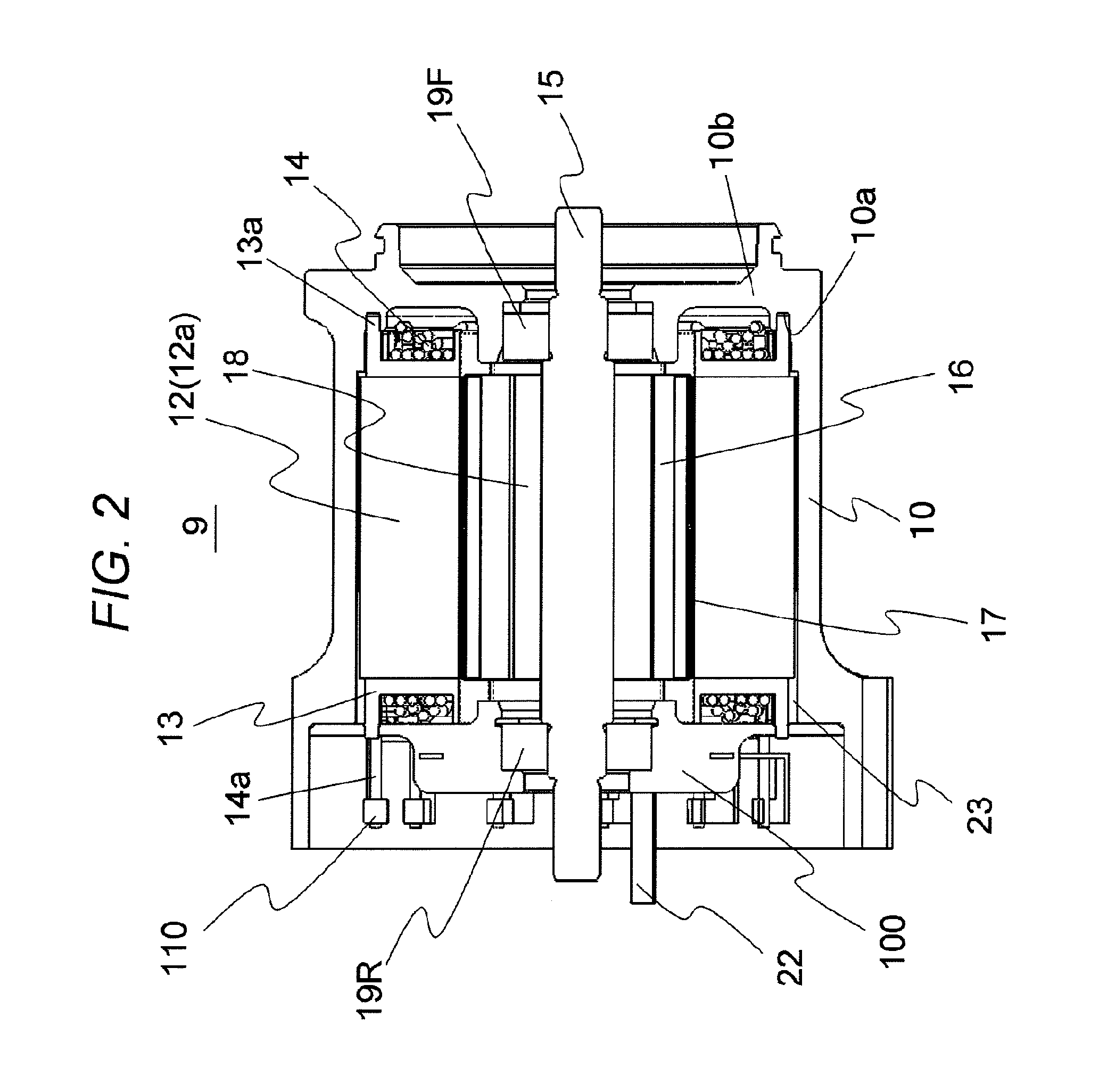
An electrical motor includes: a cylindrical stator core arranged so as to surround a periphery of a rotor via a space, and having a plurality of teeth formed in an inner periphery thereof; a bobbin installed in each of the plurality of teeth; a coil wound around each of the bobbins installed in the teeth; a bottomed cylindrical chassis having a bottom faced with one of end portions in the axial direction of the stator core, and holding an outer periphery of the stator core; and a busbar mold provided with a busbar terminal. An engaging hole is formed at least in either the bottom or the busbar mold at a position facing the bobbin, and an engaging projection that engages with the engaging hole is formed in an opposing part that faces the engaging hole in the bobbin.

Description

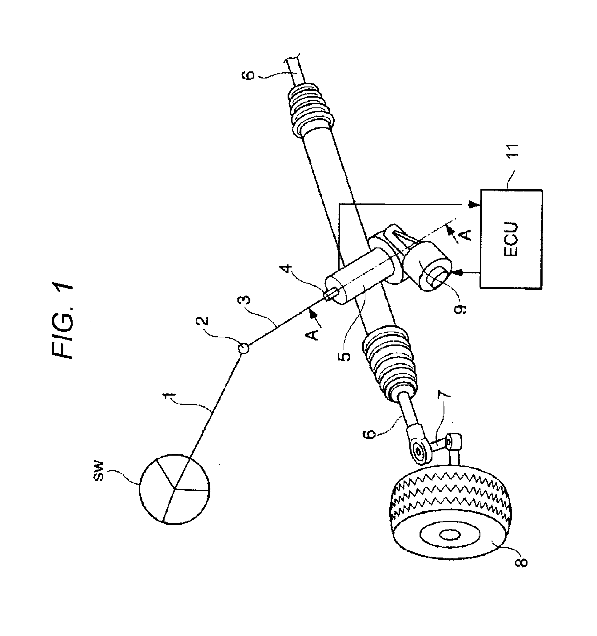
BACKGROUND OF THE INVENTION[0001]1. Field of the Invention[0002]The present invention relates to an on-vehicle rotary electric machine, and an electric power steering system having the same.[0003]2. Description of the Related Art[0004]In an on-vehicle rotary electric machine such as an electrical motor for power steering, an inner rotor-type rotary electric machine having a rotor arranged at the center of a stator core held by a chassis is commonly used. Shrink-fit or press-fit is often used to fix the stator core to the chassis.[0005]Due to a weight-saving demand, the chassis of the on-vehicle rotary electric machine is often formed by die-casting of aluminum, while the stator core is formed of a magnetic steel sheet. Therefore, when a temperature of the electrical motor becomes higher than expected, due to a difference in linear expansion coefficient between the chassis and the stator core, there is a problem in that the holding power by interference between the chassis and the st...

Claims


Application Information

Patent Timeline
IPC IPC(8): H02K3/34B62D5/04
CPCH02K3/345H02K3/522B62D5/0421
Inventor NAKAYAMA, KENJIKAWASAKI, SHOZOKANAZAWA, HIROSHIHAMADA, YASUNAGA
Owner HITACHI AUTOMOTIVE SYST LTD
Why Eureka
Try Eureka