Oil-containing wastewater treatment system

Inactive Publication Date: 2013-10-10
SUMITOMO ELECTRIC IND LTD
View PDF0 Cites 10 Cited by
  • Summary
  • Abstract
  • Description
  • Claims
  • Application Information

AI Technical Summary

Benefits of technology

[0020]As described above, according to the oil-containing wastewater treatment system of the present invention, a return pipe is arranged between a separation tank on the upstream side and a membrane filtration tank on the downstream side to supply a circulating flow to a membrane separation module disposed in the membrane filtration tank, and an upward flow of air bubbles by aeration and a cleaning effect of a surface of a membrane due to vibrations are added from a lower portion of the membrane separation module. With this structure, a stable filtration performance of the membrane is maintained and floating oil is transferred from the membrane filtration tank to the separation tank to remove the oil in the membrane filtration tank. In addition, unfiltered water containing air bubbles is circulated from the membrane filtration tank to the separation tank. Accordingly, air bubbles can be present in the separation tank without providing a diffuser in the separation tank, oil is allowed to adhere to the air bubbles during rising of the

Problems solved by technology

However, in such a treatment system in which a plurality of wastewater treatment processes are successively performed, the amount of water that can be treated decreases as the treatment processes proceed.
Thus, such a treatment system has a problem in that, when oil-containing was

Method used


Image

  • Oil-containing wastewater treatment system
  • Oil-containing wastewater treatment system
  • Oil-containing wastewater treatment system

Examples


Example

[0028]Embodiments of the present invention will now be described with reference to the drawings.

[0029]FIGS. 1 and 2 illustrate an embodiment of the present invention.

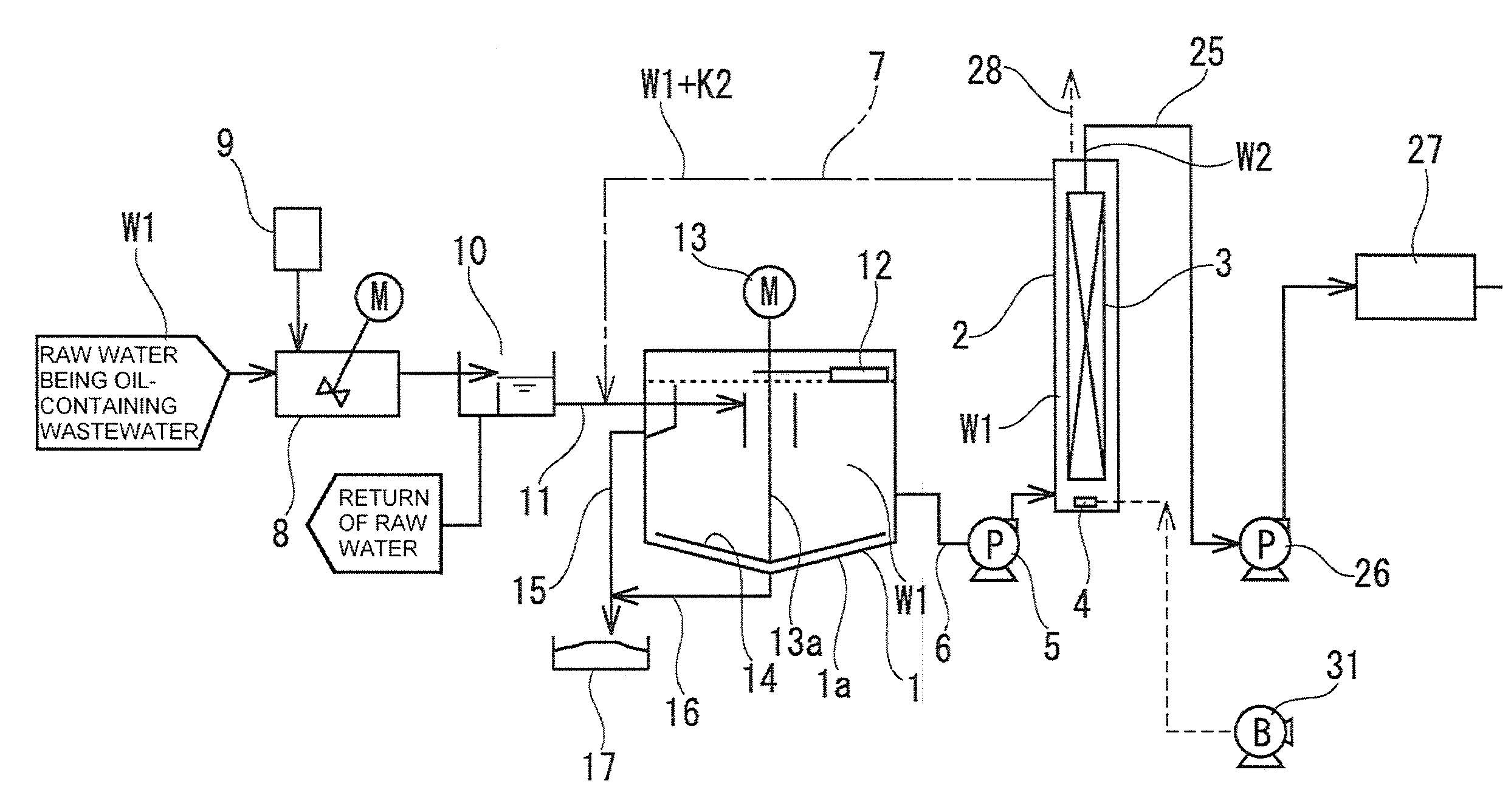
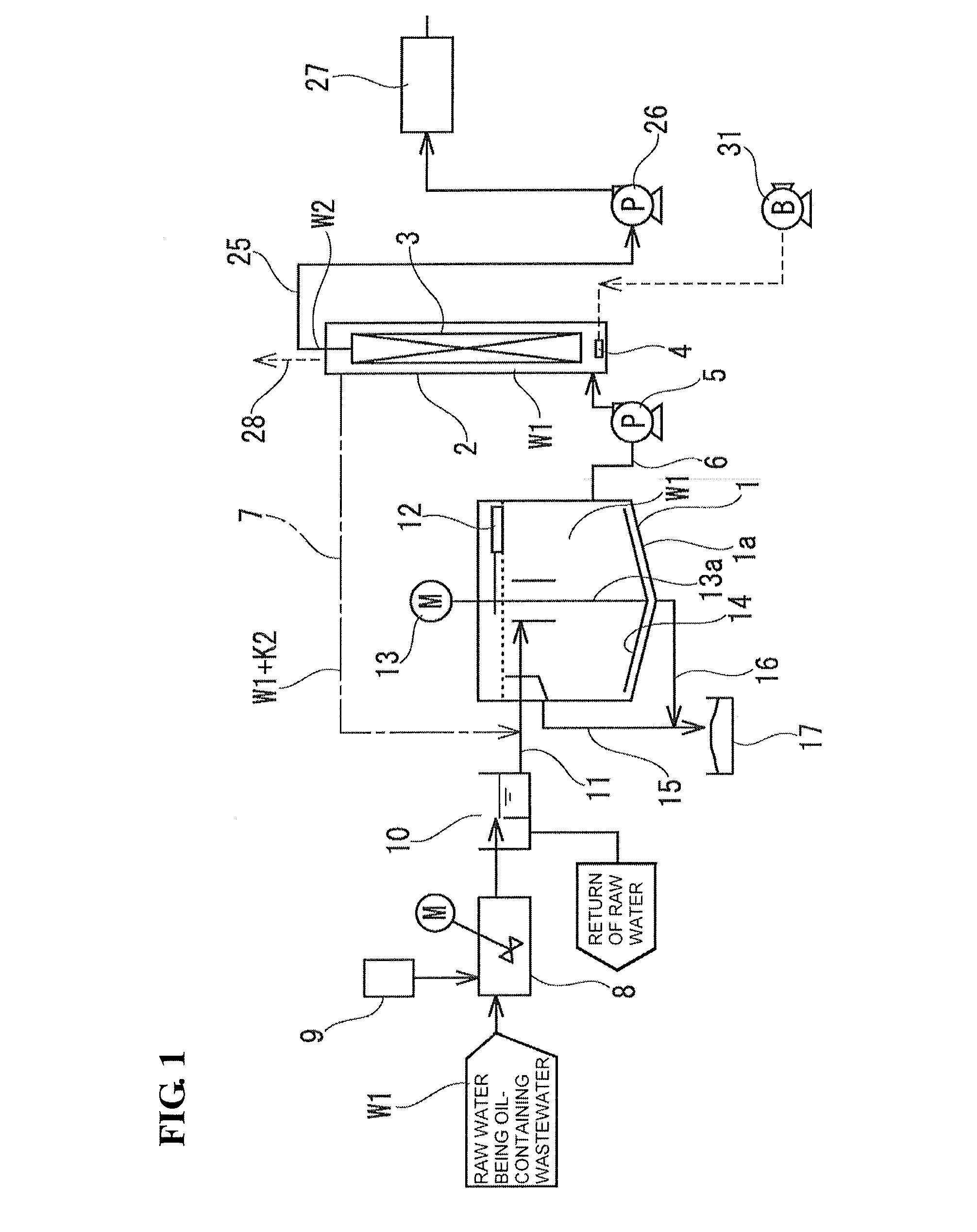
[0030]In the overall view illustrated in FIG. 1, reference numeral 1 denotes a separation tank that separates foreign substances by flotation and sedimentation, and reference numeral 2 denotes a membrane filtration tank that filters foreign substances with a membrane.

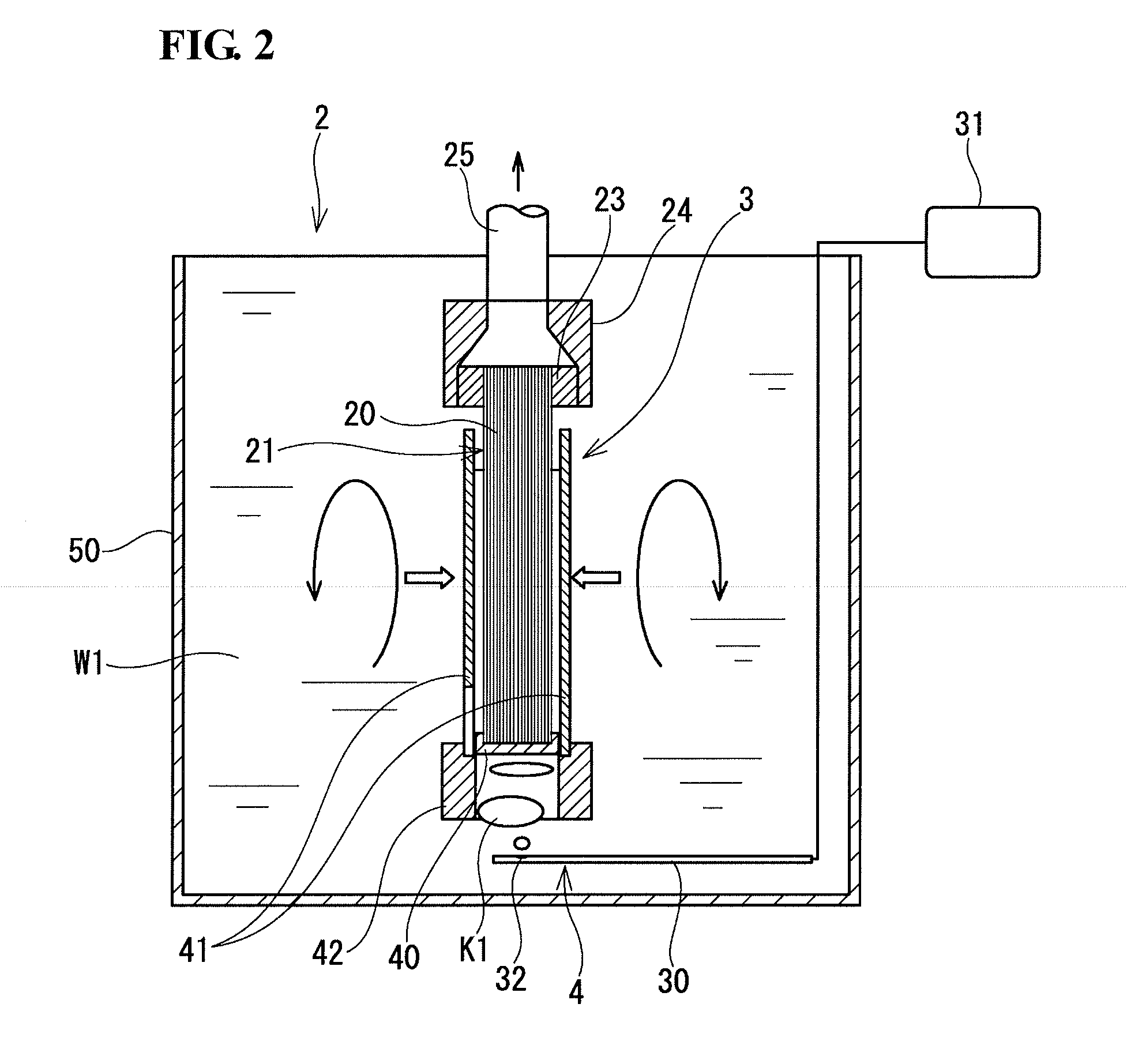
[0031]The membrane filtration tank 2 houses a hollow fiber membrane module (membrane separation module) 3 and a diffuser 4 that generates air bubbles, the diffuser 4 being disposed below the hollow fiber membrane module 3.

[0032]A middle region of the separation tank 1 in the vertical direction is connected to a lower region of the membrane filtration tank 2 through a supply pipe 6 with a pump 5 therebetween. In addition, a return pipe 7 that connects an upper region of the membrane filtration tank 2 to an upper region of the separation tank 1 is provided so...


PUM

PropertyMeasurementUnit
Diameteraaaaaaaaaa

Abstract

Devices used in an oil-containing wastewater treatment system are simplified by efficiently combining differences in processes used in the system.
The oil-containing wastewater treatment system includes a separation tank that separates oil by flotation, the separation tank being arranged in a supply path of raw water which is oil-containing wastewater; a membrane filtration tank that is arranged on the downstream of the separation tank and that includes therein a membrane separation module including a hollow fiber membrane or a flat sheet membrane, and a diffuser for generating air bubbles, the diffuser being disposed below the membrane separation module; a supply pipe that supplies the raw water from the separation tank to the membrane filtration tank through a circulating pump; and a return pipe that returns unfiltered water containing the oil and air bubbles from the membrane filtration tank to the separation tank.

Description

TECHNICAL FIELD[0001]The present invention relates to an oil-containing wastewater treatment system, and in particular, to an oil-containing wastewater treatment system which combines separation in a pre-treatment process including flotation and sedimentation with membrane filtration in a post-treatment process and in which an efficient treatment is performed by combining the function in the pre-treatment process with the function in the post-treatment process.BACKGROUND ART[0002]Various treatment apparatuses and treatment methods for removing oil from oil-containing wastewater have been proposed. In general, in oil-containing wastewater treatment, a pre-treatment including coagulating sedimentation / pressure flotation or the like is performed, and a post-treatment including filtration, a treatment with activated carbon, etc. is then performed. However, in such a treatment system in which a plurality of wastewater treatment processes are successively performed, the amount of water th...

Claims


Application Information

Patent Timeline
IPC IPC(8): C02F1/44
CPCB01D21/06C02F2101/32B01D71/36B01D71/68C02F1/24C02F1/40C02F1/44B01D61/16B01D63/02B01D63/08B01D2311/04B01D2315/06B01D2321/185B01D65/02C02F2001/007B01D21/01B01D21/2427B01D21/2433B01D21/2488B01D61/147C02F1/444C02F9/00B01D2311/00B01D21/0084B01D63/031
Inventor USHIKOSHI, KENICHIMORITA, TORUIDA, KIYOSHIMIZUTANI, TEIZO
Owner SUMITOMO ELECTRIC IND LTD
Why Eureka
Try Eureka