Seat structure member and vehicle seat

a seat structure and seat technology, applied in the field of seat structure members and vehicle seats, can solve the problems of the seat sa rising and the structure with a bit of deterioration in seat performance, and achieve the effect of good performan

Inactive Publication Date: 2013-10-10
TOYOTA BOSHOKU KK
View PDF8 Cites 8 Cited by
  • Summary
  • Abstract
  • Description
  • Claims
  • Application Information

AI Technical Summary

Benefits of technology

[0009]One aspect of the invention relates to a vehicle seat that includes a seat structure member, and a blowing apparatus that is arranged on the seat structure member. The seat structure member includes a cushion made of resin foam material, a flow path portion of the cushion, through which air passes, and a cover that covers the cushion. Air that is blown from the blowing apparatus is blown to the cover side via the flow path portion. Also, in this aspect, the cushion described above is formed inside the cavity of the molding apparatus, and the flow path portion is formed by the protruding portion that is arranged inside the cavity. It is desirable that with this kind of aspect, the cover and the cushion that has the flow path portion are able to be integrated with good performance.

Problems solved by technology

Therefore, with this structure, the protruding portion Px (a portion that feels like a foreign body) is formed on the cushion Pa, and this protruding portion Px may cause the cover Sa to rise up (i.e., results in a structure with somewhat diminished seat performance).

Method used


Image

  • Seat structure member and vehicle seat
  • Seat structure member and vehicle seat
  • Seat structure member and vehicle seat

Examples


Embodiment Construction

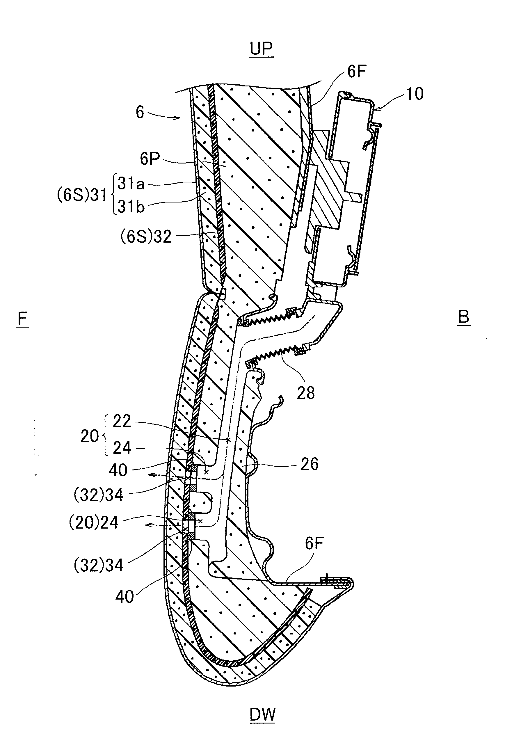
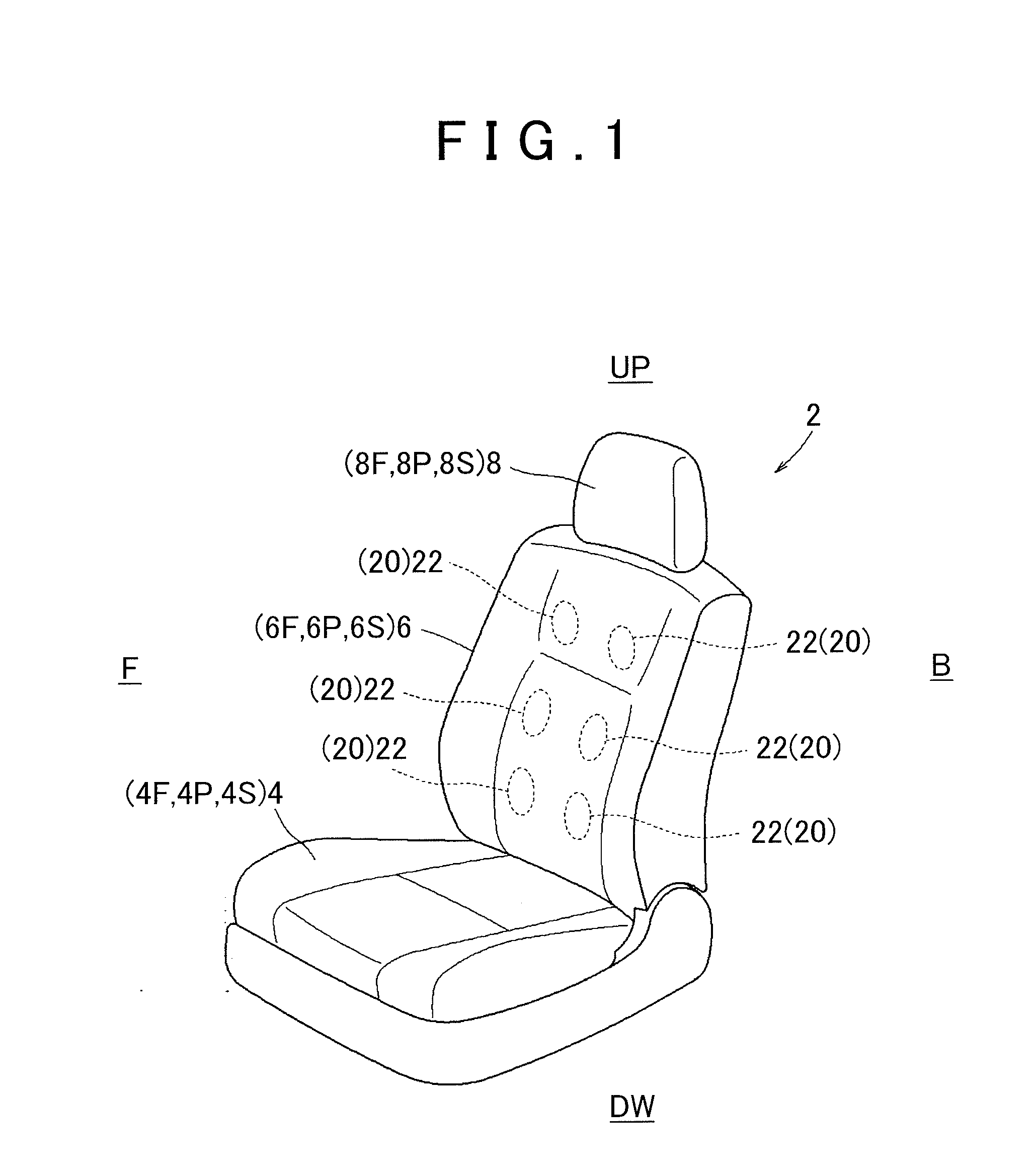
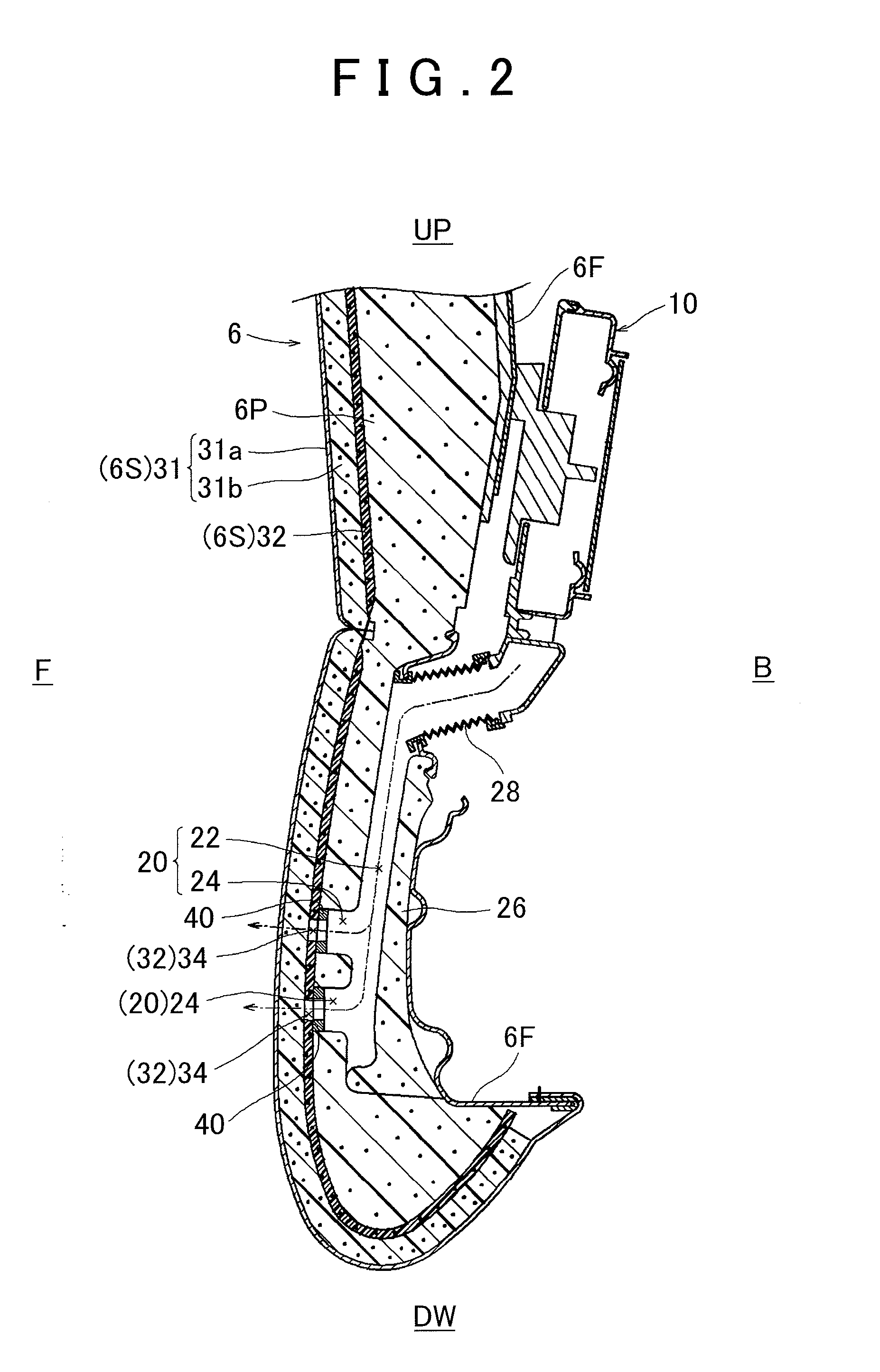
[0024]Hereinafter, example embodiments of the invention will be described with reference to FIGS. 1 to 7. In the drawings, reference character F denotes a forward direction with respect to each member, reference character B denotes a rearward direction with respect to each member, reference character UP denotes an upward direction with respect to each member, and reference character DW denotes a downward direction with respect to each member, as appropriate. A vehicle seat 2 in FIG. 1 has a seat cushion 4, a seat back 6, and a headrest 8. These seat structure members each have a frame member (4F, 6F, 8F) that forms a seat frame, a cushion (4P, 6P, 8P) that forms the outer shape of the seat, and a cover (4S, 6S, 8S) that covers the cushion. Here, the frame members (4F, 6F) are frame bodies that typically have a generally rectangular shape, and support the cushions (4P, 6P).

[0025]The seat back 6 has the structures described above (6F, 6P, 6S), a blowing apparatus 10, and a flow path p...


PUM


Abstract

A cover has a breathable first portion arranged on a seating side of a seat structure member, a second portion that is laminated to the first portion and inhibits penetration of resin foam material, and a passage portion through which air passes that is provided on the second portion. A protruding portion is arranged face-to-face with the passage portion while the cover is arranged in a cavity, and the cushion is formed with an interposed member that is less rigid than the cover being interposed between the passage portion and the protruding portion.

Description

INCORPORATION BY REFERENCE[0001]The disclosure of Japanese Patent Application No. 2012-088199 filed on Apr. 9, 2012 including the specification, drawings and abstract is incorporated herein by reference in its entirety.BACKGROUND OF THE INVENTION[0002]1. Field of the Invention[0003]The invention relates to a seat structure member provided with a blowing apparatus, a cushion capable of elastically supporting an occupant, and a flow path portion (i.e., a portion through which air from the blowing apparatus is able to pass) of the cushion, as well as to a vehicle seat.[0004]2. Description of Related Art[0005]Japanese Patent Application Publication No. 2008-142244 (JP 2008-142244 A) describes one such known vehicle seat that has a seat cushion and a seat back. The seat cushion and the seat back (both seat structure members) each have a cushion and a cover. The cover is a bag-like member capable of covering the cushion, and is made of breathable cloth material (such as fabric). The cushi...

Claims


Application Information

Patent Timeline
Patent Type & Authority Applications(United States)
IPC IPC(8): B60N2/56A47C7/74
CPCB60N2/5657B60N2/7017A47C7/744
Inventor OTA, HIROKI
Owner TOYOTA BOSHOKU KK
Why Eureka
Try Eureka