Cooperative systems and methods for tdoa-based emitter location

a technology of electromagnetic radiation and co-operation, applied in the direction of direction finders, radio wave direction/deviation determination systems, instruments, etc., to achieve the effect of accurate resolution of signal arrival timing relationships

Inactive Publication Date: 2013-10-10
L 3 COMM INTEGRATED SYST
View PDF2 Cites 95 Cited by
  • Summary
  • Abstract
  • Description
  • Claims
  • Application Information

AI Technical Summary

Benefits of technology

[0008]Disclosed herein are systems and methods that may be implemented to determine the location of an emitter of electromagnetic radiation (e.g., RF signal emitter, visible light spectrum emitter, etc.) having an unknown location, using a cooperative TDOA-based location methodology. The cooperative TDOA-based location methodology (e.g., such as TDOA/TDOA, TDOA/FDOA, etc.) may be implemented using at least one cooperative transmitter that transmits a cooperative electromagnetic radiation (EM) signal f

Problems solved by technology

However, only one of these possible geolocations is real, the other possible geolocations in

Method used


Image

  • Cooperative systems and methods for tdoa-based emitter location
  • Cooperative systems and methods for tdoa-based emitter location
  • Cooperative systems and methods for tdoa-based emitter location

Examples


Embodiment Construction

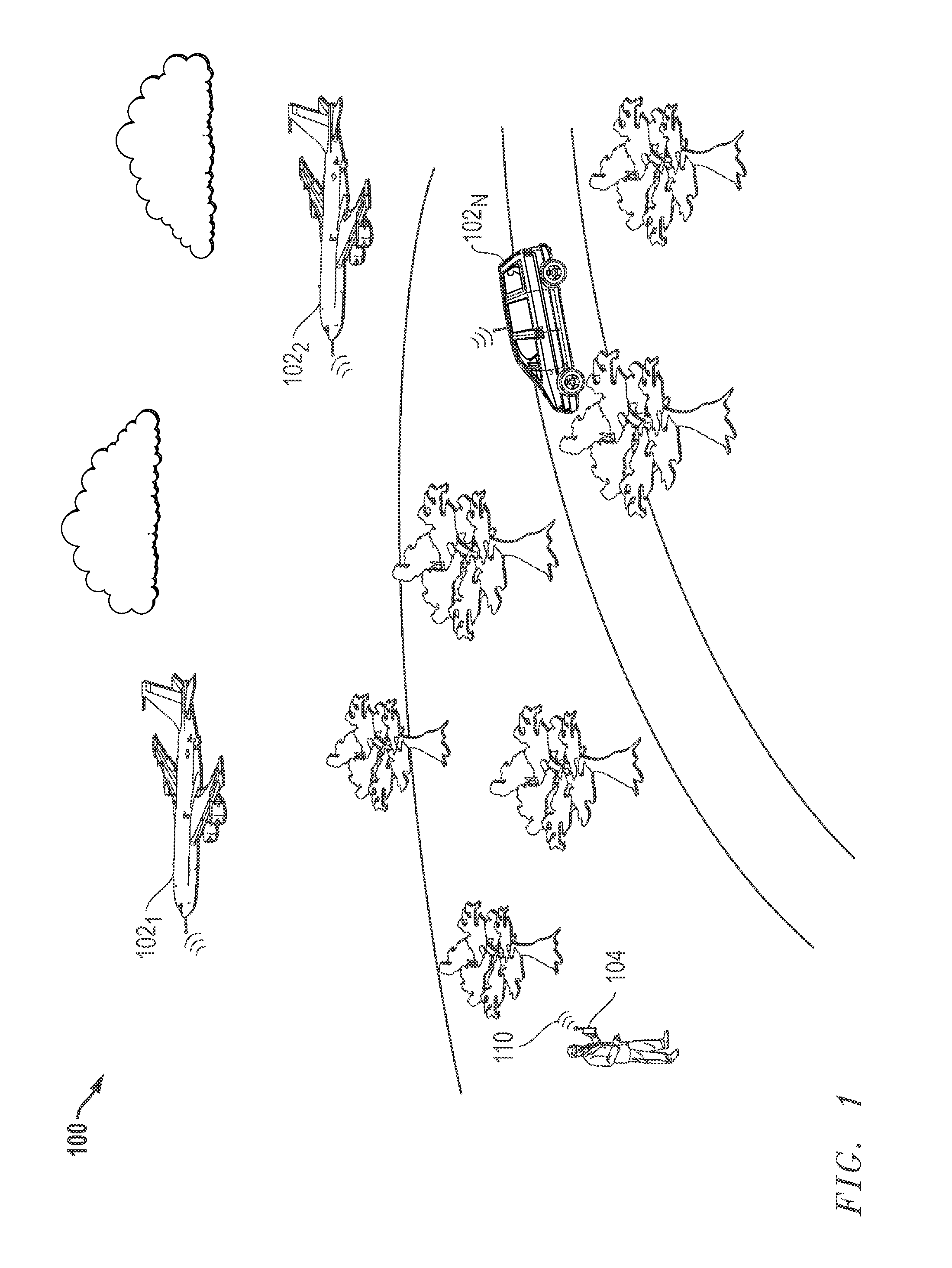
[0030]FIG. 1 illustrates one exemplary embodiment of an EM emissions environment 100 (in this case a radio communication environment) in which an emitter in the form of transmitter 104 at an unknown location is transmitting a target EM signal of interest 110 (TXunknown), e.g., in this case a radio frequency (RF) signal. In the illustrated embodiment, the illustrated emitter 104 is a ground-based mobile emitter (e.g., cell phone, push to talk radio, etc.) carried by a human being that is stationary and emitting from a fixed location. However, it will be understood that the disclosed systems and methods may be practiced in radio communication environments in which any type, number and / or combination of different types of emitters are transmitting on a one or more frequencies including, but are not limited to, base stations of a cellular telephone network, cell phone devices, weather broadcast stations, radar signal sources, microwave sources, etc. Furthermore, besides being hand carri...


PUM


Abstract

Systems and methods that may be implemented to determine the location of an emitter of electromagnetic radiation having an unknown location, using a cooperative TDOA-based location methodology. The cooperative TDOA-based location methodology (e.g., such as TDOA/TDOA, TDOA/FDOA, etc.) may be implemented using at least one cooperative transmitter that transmits a cooperative electromagnetic (EM) signal from a known location that is received at multiple different EM sensing platforms that are also each of known location. The known geolocation of the cooperative transmitter may be used to resolve the signal arrival timing relationships between the different sensing platforms that is utilized to determine the location of another EM transmitter of unknown location.

Description

BACKGROUND OF THE INVENTION[0001]1. Field of the Invention[0002]This invention relates generally to location of emitters of electromagnetic radiation, and in particular, to Time Difference of Arrival (“TDOA”)-based location of emitters of electromagnetic radiation.[0003]2. Description of the Related Art[0004]TDOA techniques have been employed in the past to determine the location of emitters of electromagnetic radiation, such as radio frequency (“RF”) emissions. Using the TDOA technique, the time difference (TDOA) in reception of a radio signal received at multiple spaced sensing platforms may be used to define a hyperboloid upon which the RF emitter of interest is located. TDOA may be used to calculate the geolocation of the RF transmitter if three or more sensing platforms simultaneously capture the radio signal, and if the difference in the times of arrival of the captured radio signal at the different sensing platforms can be accurately determined.[0005]Frequency difference (FDO...

Claims


Application Information

Patent Timeline
IPC IPC(8): G01S1/04
CPCG01S1/04G01S5/06G01S5/0221G01S5/0081G01S5/02216
Inventor STROUD, KEN A.
Owner L 3 COMM INTEGRATED SYST
Why Eureka
Try Eureka