Work vehicle

Active Publication Date: 2013-10-10
KANZAKI KOKYUKOKI MFG
View PDF7 Cites 30 Cited by
  • Summary
  • Abstract
  • Description
  • Claims
  • Application Information

AI Technical Summary

Benefits of technology

[0010]An advantage of the present invention regarding a work vehicle is that power saving can be achieved, and that a structure capable of obtaining a desirable after-operation state, for example, a lawn state, with an efficient operation can be realized.
[0011]A first work vehicle according to the present invention is a work vehicle including a driving wheel motor for driving at least one driving wheel, a working implement-related motor for driving at least one working implement, and at least one controller, wherein the at least one controller sets, upon satisfaction of a predetermined condition set in advance, a relationship between vehicle speed of the work vehicle and working implement-related target rotational speed of the working implement-related motor to a working travelling cooperative relationship according to which the working implement-related target rotational speed is increased according to an increase in the vehicle speed at least within a predetermined vehicle speed range of the work vehicle, and controls the working implement-related motor to implement a working travelling cooperative mode in which the working implement-related motor is driven at the working implement-related target rotational speed based on the working travelling cooperative relationship.
[0012]Also, a second work vehicle according to the present invention is a work vehicle including a driving wheel motor for driving at least one driving whee

Problems solved by technology

Accordingly, in the case where the vehicle speed is high, the resistance of the lawn grass is great, and there is a possibility that performing mowing once will not be enough to obtain a neat lawn, i.e. a desirable state of lawn where most of the lawn grass is cut to a desirable length.
Wit

Method used


Image

  • Work vehicle
  • Work vehicle
  • Work vehicle

Examples


Embodiment Construction

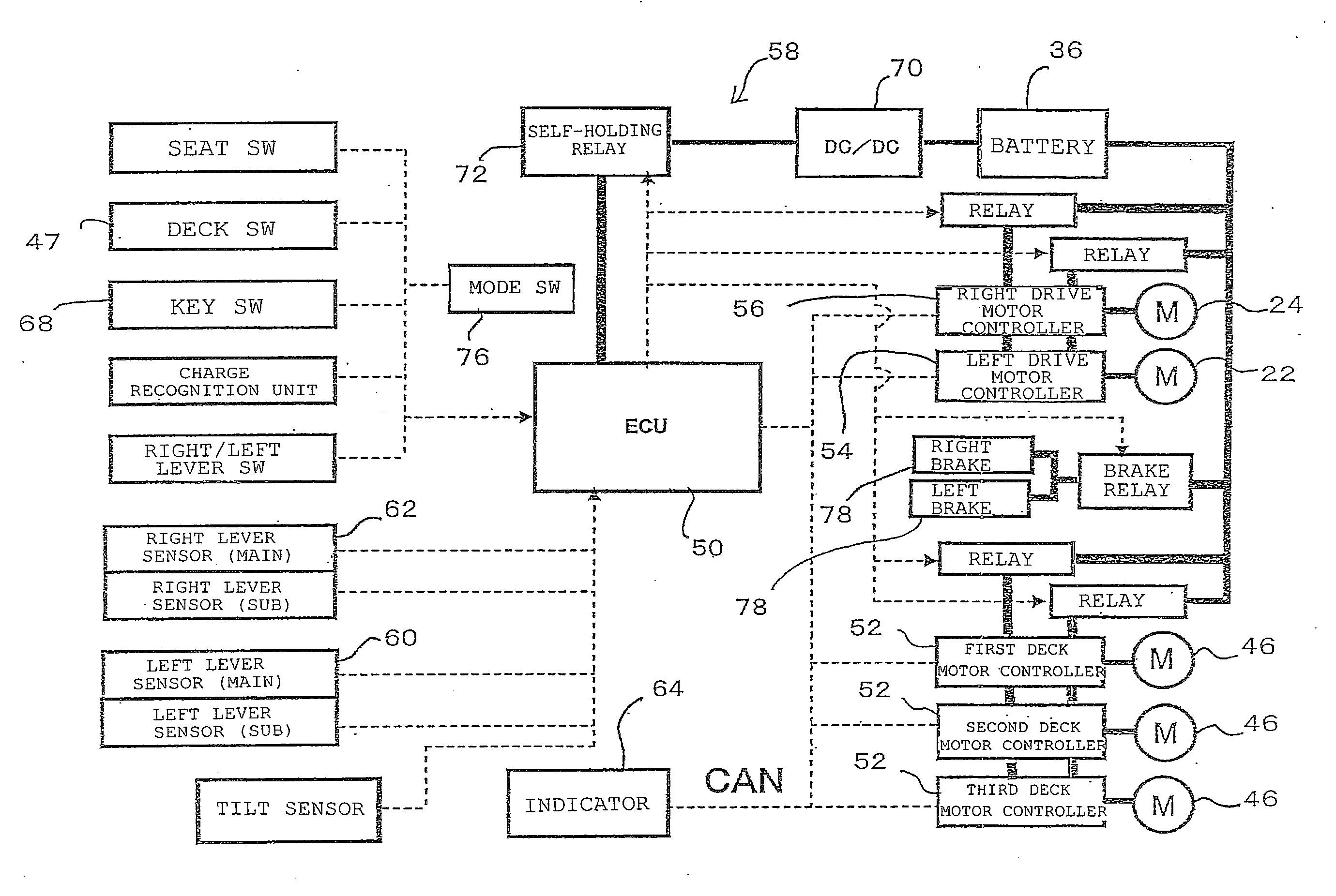
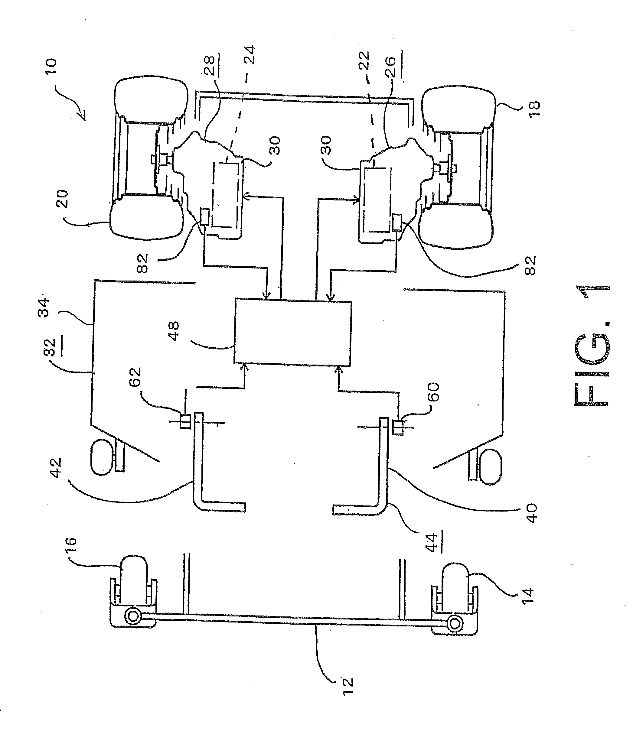
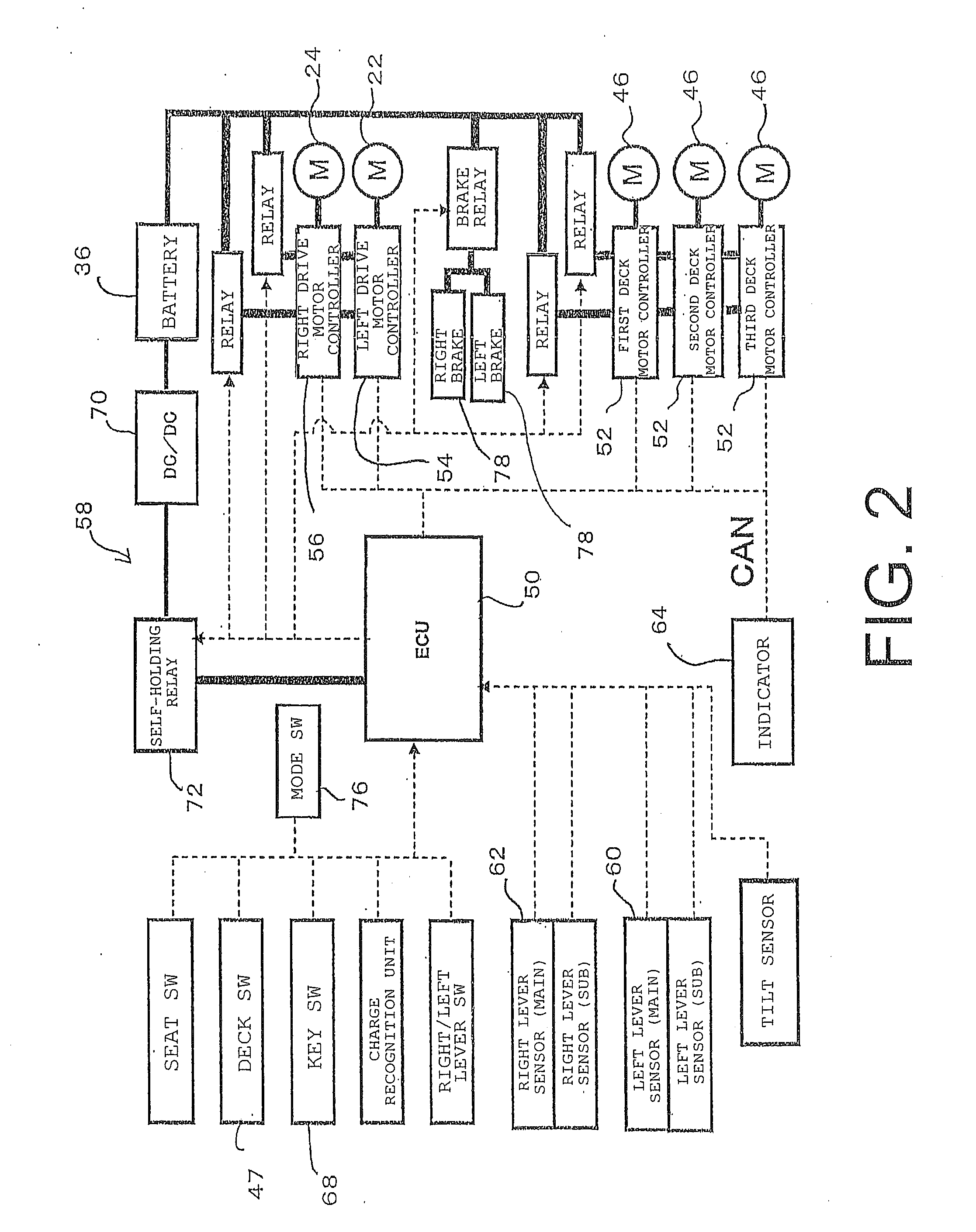
[0033]Hereinafter, an embodiment according to the present invention will be described in detail based on the drawings. FIGS. 1 to 7 show one embodiment of the present invention. FIG. 1 is a schematic view of a structure, seen from above, of a riding mower of the embodiment according to the present invention. Additionally, FIG. 1 shows a case where a left / right lever-type operator 44 including two, left and right operation levers 40 and 42 is used as a structure having the functions of both a turning instruction device and an acceleration instruction device, but it is also possible to use a steering operator which is a steering handle as the turning instruction device, and an accelerator pedal which is an operator provided at the front side of a seat as the acceleration instruction device. Also, a case is described below where three deck motors are provided on a riding mower 10, but one, two, or four or more deck motors may be provided on the riding mower.

[0034]As shown in FIG. 1, th...


PUM


Abstract

A work vehicle includes a driving wheel motor for driving at least one driving wheel, a working implement-related motor for driving at least one working implement, and at least one controller. The at least one controller sets, upon satisfaction of a predetermined condition set in advance, a relationship between vehicle speed of the work vehicle and working implement-related target rotational speed of the working implement-related motor to a working travelling cooperative relationship according to which the working implement-related target rotational speed is increased according to an increase in the vehicle speed at least within a predetermined vehicle speed range of the work vehicle, and controls the working implement-related motor to implement a working travelling cooperative mode in which the working implement-related motor is driven at the working implement-related target rotational speed based on the working travelling cooperative relationship.

Description

PRIORITY INFORMATION[0001]This application claims priority to Japanese Patent Applications No. 2012-055427 filed on Mar. 13, 2012 and No. 2012-055975 filed on Mar. 13, 2012, both of which are incorporated herein by reference in their entirety.BACKGROUND[0002]1. Technical Field[0003]The present invention relates to a work vehicle including a driving wheel motor for driving at least one driving wheel, a working implement-related motor for driving at least one working implement, and at least one controller.[0004]2. Related Art[0005]Riding mowers including a working implement which is driven to perform mowing are conventionally known. Also, there are conceivable riding mowers, such as the riding mowers mentioned above, including left and right wheels which are main driving wheels that are driven by independent or common motors such as electric motors, hydraulic motors or the like, and a steering wheel such as a caster wheel.[0006]For example, there is a riding mower capable of autonomou...

Claims


Application Information

Patent Timeline
IPC IPC(8): A01D34/00
CPCB60W10/30B60W30/1886B60W2510/305B60W2520/10B60W2300/156B60W2710/30A01D34/006B60W10/08B60W30/18B60Y2200/223A01D34/76A01D34/60A01D34/58A01D34/64A01D34/56A01D34/80A01D34/78
Inventor HASHIMA, HIROAKIWANG, HONGKUN
Owner KANZAKI KOKYUKOKI MFG
Why Eureka
Try Eureka