Electromagnetic Band Gap Structure and Method for Enhancing the Functionality of Electromagnetic Band Gap Structures

a technology of electromagnetic band gap and structure, applied in the field of electromagnetic band gap structure, antenna system, can solve the problems of affecting the performance of the antenna system, requiring a system that is very large, and requiring compact structures that are typically not available for design using such an ebg structur

Active Publication Date: 2013-10-10
LOCKHEED MARTIN CORP +1
View PDF0 Cites 17 Cited by
  • Summary
  • Abstract
  • Description
  • Claims
  • Application Information

AI Technical Summary

Benefits of technology

[0010]Electromagnetic band gap structures are also provided that may be designed based on an embodiment of our method and fabricated using an embodiment our method. For instance, an electromagnetic band structure may comprise a body defining a plurality of unit cells. Each of the unit ce

Problems solved by technology

Undesired coupling can cause performance degradation or even damage to the underlying hardware of an antenna system.
However, use of multiple cascaded sections requires a system that is very large due to the need for a sub-structure to cover each frequency range.
Compact structures are typically not available f

Method used


Image

  • Electromagnetic Band Gap Structure and Method for Enhancing the Functionality of Electromagnetic Band Gap Structures
  • Electromagnetic Band Gap Structure and Method for Enhancing the Functionality of Electromagnetic Band Gap Structures
  • Electromagnetic Band Gap Structure and Method for Enhancing the Functionality of Electromagnetic Band Gap Structures

Examples


Embodiment Construction

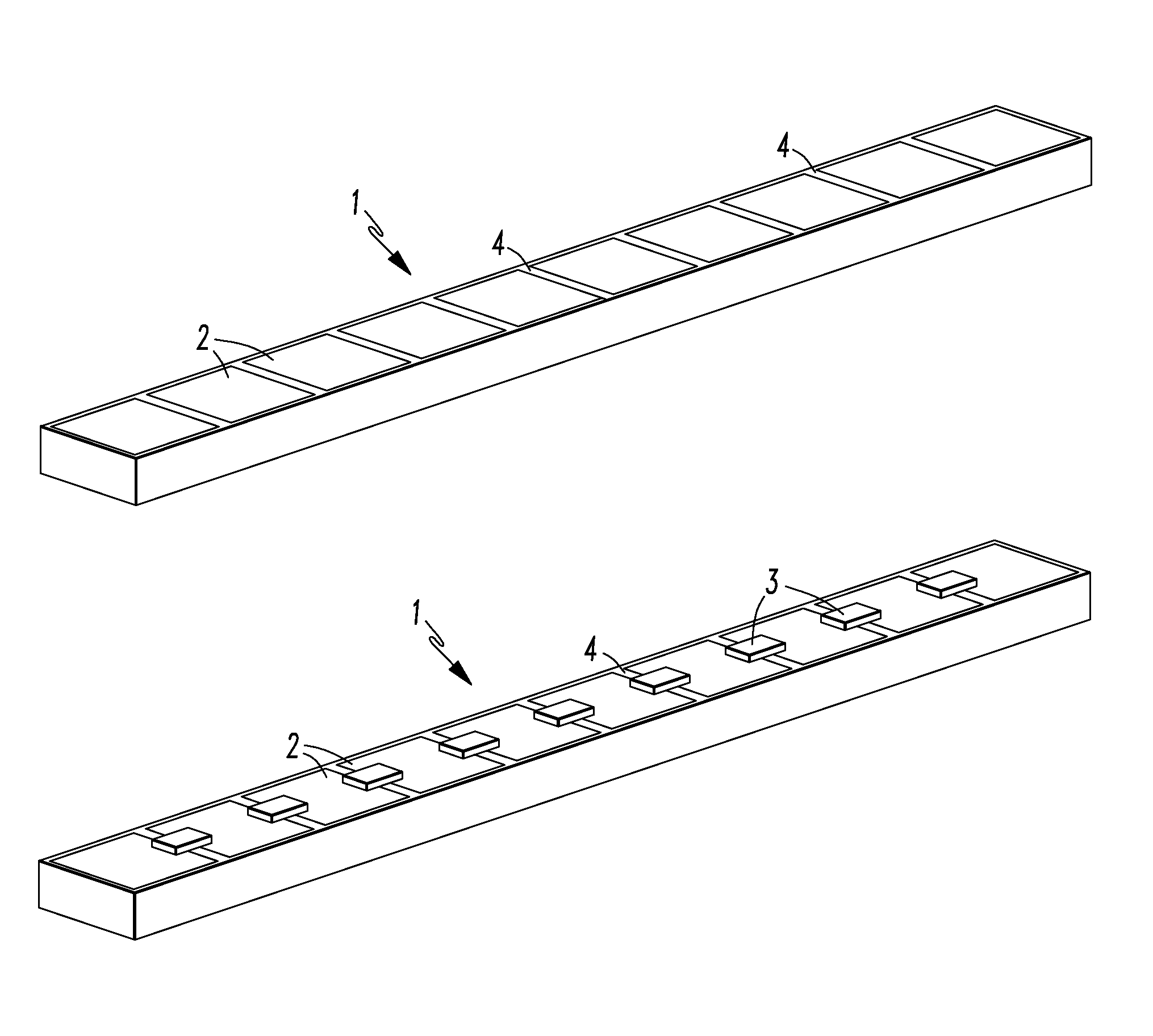
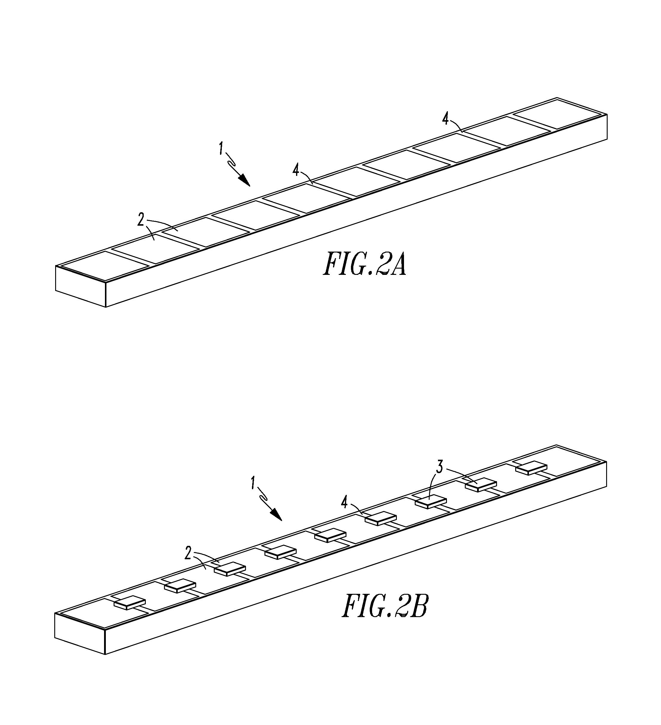
[0045]Referring to FIGS. 1-2B, an embodiment of our electromagnetic band gap structure 1 for inclusion in an antenna system or antenna assembly is shown in FIG. 2B. An image of the underlying structure prior to inclusion of scattering elements sized and configured to provide a desired scattering effect is shown in FIG. 2A. The underlying structure contains a plurality of identical unit cells 2. Each unit cell includes a metallic patch and a via. The metallic patch 2a of each unit cell 2 is separated by a gap, groove or channel 4.

[0046]The scattering elements included in the embodiment of the EBG structure shown in FIG. 2B are capacitors 3 that are positioned between different metallic patches 2 of the electromagnetic band gap structure 1 to provide a desired scattering effect. Each of the capacitors 3 extend from one metallic patch over the gap, channel, or other type of aperture 4 and to an immediately adjacent unit cell. It is also contemplated that at least a portion of each capa...


PUM


Abstract

A method for making an electromagnetic band gap structure includes performing a single full wave simulation for the structure using a computer to perform the simulation, extracting a multiple port scattering matrix based on the single full wave simulation using a computer, and measuring or estimating a transmission of waves across the body between a first port and a second port of the body. The body has multiple ports between the first port and the second port that are defined by scattering elements using the computer. The matrix may be reduced to a two by two matrix recursively one dimension at a time using the computer.

Description

CROSS-REFERENCE TO RELATED APPLICATIONS[0001]The present application claims priority to U.S. Provisional Patent Application No. 61 / 622,068, which was filed on Apr. 10, 2012. The entirety of U.S. Provisional Patent Application No. 61 / 622,068 is incorporated by reference herein.FIELD OF INVENTION[0002]The present invention relates to electromagnetic band gap structures, antenna systems that utilize at least one electromagnetic band gap structure and methods of making, designing and enhancing such electromagnetic band gap structures.BACKGROUND OF THE INVENTION[0003]In many antenna systems, the ability to control mutual coupling between elements in an antenna array or between separate arrays is often of critical importance. As many antenna systems need to be operable over a broad frequency range, such coupling of elements must also be maintained over a broad frequency range to meet design objectives. Undesired coupling can cause performance degradation or even damage to the underlying h...

Claims


Application Information

Patent Timeline
IPC IPC(8): G06F17/50H01Q15/02
CPCG06F17/5009G06F17/5036H01Q15/0066H01Q15/02G06F30/367H01Q1/521H04B2203/5483G06F17/12H05K2201/09618H04B2203/5425H04B1/40G06F30/20G06F30/36G06F30/373
Inventor WERNER, DOUGLAS H.MARTIN, SPENCERLIER, ERIKBRAY, MATTHEW
Owner LOCKHEED MARTIN CORP
Why Eureka
Try Eureka