

Valve timing control device
- Summary
- Abstract
- Description
- Claims
- Application Information
AI Technical Summary
Benefits of technology
Problems solved by technology
Method used
Image

Examples
first embodiment
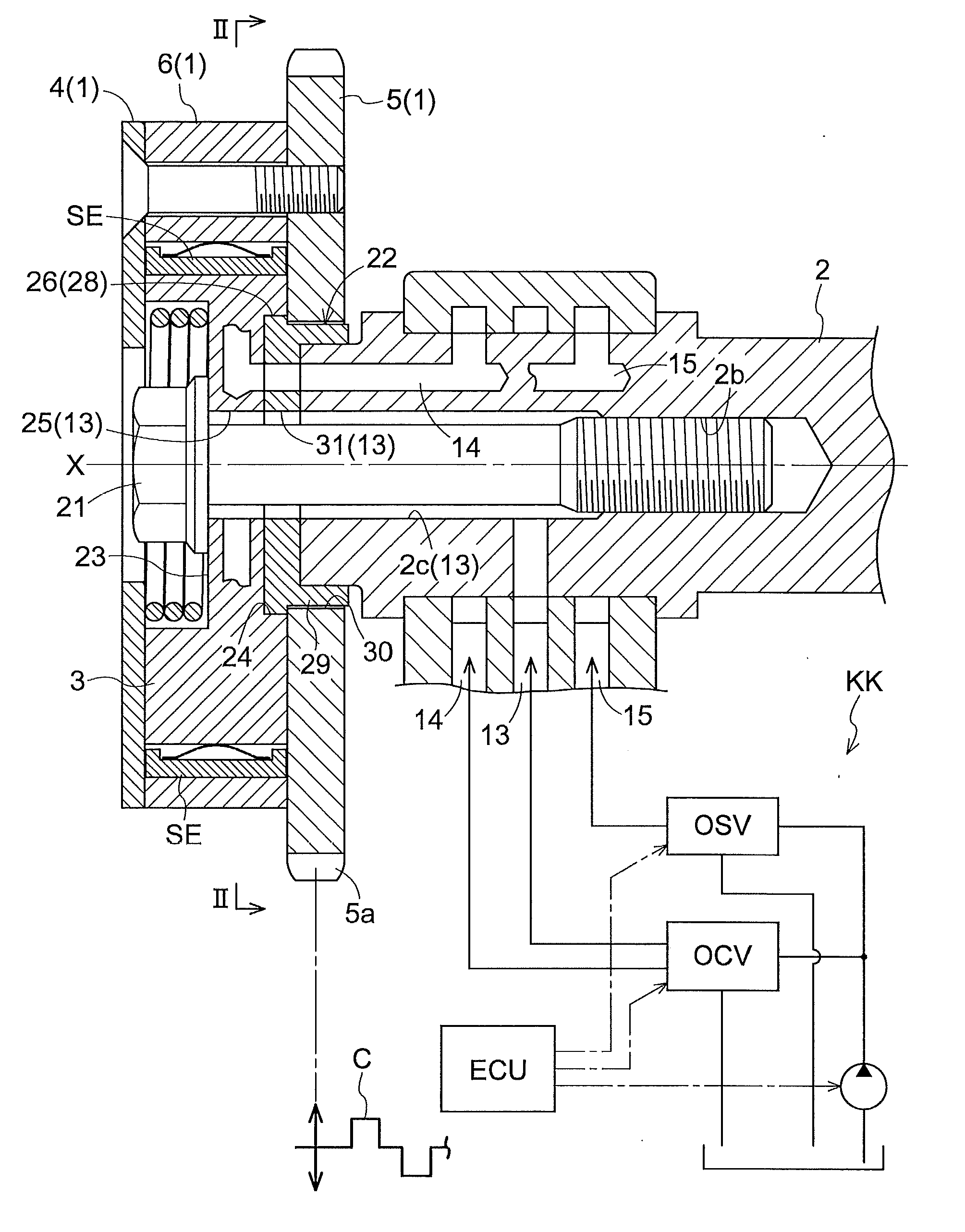
[0038]A valve timing control device according to an embodiment of the present invention that is applied to an automobile engine will be described hereinafter in reference to FIGS. 1 and 5.
[Overall Configuration]
[0039]Referring to FIG. 1, the valve timing control device is provided with a steel housing 1 (an example of a driving rotary element) that is synchronously rotatable with a crankshaft C of an engine, and an aluminum inner rotor 3 (an example of a driven rotary element) that is synchronously rotatable with a camshaft 2 of the engine. The housing 1 and the inner rotor 3 are coaxially arranged on an axis X.
[Housing and Rotor]
[0040]Referring to FIGS. 1 to 4, the housing 1 includes a front plate 4 mounted on a front side thereof opposite to the camshaft 2, a wall 5 mounted on a rear side thereof adjacent to the camshaft 2, and an outer rotor 6 mounted between the front plate 4 and the wall 5. The front plate 4, wall 5 and outer rotor 6 are fixedly screwed. A sprocket 5a is provid...
second embodiment
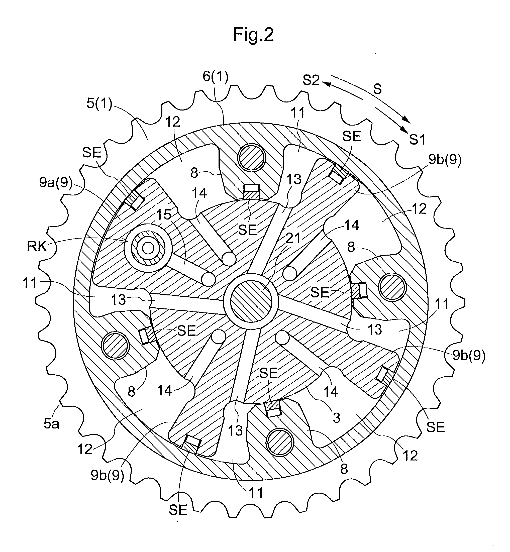
[0055]Referring to FIGS. 6 and 7, a plurality of fitting segments 28 are formed in the connecting element 22. The fitting segments 28 are formed at intervals in an inner circumference of the second hollow 24 along the rotational direction S. For example, the phase of the adjacent fitting segments 28 has an angle of 90 degrees about the rotational axis. Further, a cutaway segment 27 is defined between the adjacent fitting segments 28.
[Positional Relationship Between Fitting Segment and Second Partition]
[0056]As shown in the arrangement shown in FIG. 7, none of the fitting segments 28 may overlap any of the second partitions 9, for example. When the connecting element 22 is press-fitted into the second hollow 24, the portions of the inner rotor 3 corresponding to the fitting segments are somewhat deformed to be radially enlarged, but are not associated with any of the second partitions 9. Thus, none of the second partitions 9 are deformed in corners. As a result, the outward surface d...
third embodiment
[0059]Referring to FIG. 8, part of the fitting segments 28 overlaps the second partition 9 that is provided with the lock mechanism RK of the plurality of second partitions 9 in the radial direction, and the remaining fitting segments 28 do not overlap the second partitions 9 that are not provided with the lock mechanism RK. The second partition 9 that is provided with the lock mechanism RK is greater than the remaining second partitions 9 in circumferential dimension and rigidity because the lock pin should be provided. Thus, the second partition 9 that is provided with the lock mechanism RK is referred to as a high-rigidity partition 9a, while the remaining second partitions are referred to as low-rigidity partitions 9b hereinafter.
[0060]In the embodiment shown in FIG. 8, while three fitting segments 28 can be arranged so as not to overlap any of the second partitions 9, one fitting segment 28 inevitably overlaps any of the second partitions 9. In such a case, the high-rigidity pa...
PUM
 Abstract
Description
Claims
Application Information