Pressure damping device for brake system

a technology of pressure damping device and brake system, which is applied in the direction of brake system, pipe elements, piping arrangement, etc., can solve the problem that the driver cannot provide the feel of the pedal, and achieve the effect of reducing the pressure pulsation

Active Publication Date: 2013-10-17
HL MANDO CORP
View PDF10 Cites 7 Cited by
  • Summary
  • Abstract
  • Description
  • Claims
  • Application Information

AI Technical Summary

Benefits of technology

[0011]Therefore, it is an aspect of the present invention to provide a pressure damping device for a brake system that may include an air damping space provided in an oil passage ...

Problems solved by technology

However, in the pressure damping device 1 according to the related art, the pressure pulsation is reduced only by t...

Method used


Image

  • Pressure damping device for brake system
  • Pressure damping device for brake system
  • Pressure damping device for brake system

Examples


Embodiment Construction

[0025]Example embodiments of the present invention are disclosed herein. However, specific structural and functional details disclosed herein are merely representative for purposes of describing example embodiments of the present invention. Example embodiments of the present invention may be embodied in many alternate forms and should not be construed as limited to example embodiments of the present invention set forth herein.

[0026]A pressure damping device according to an embodiment of the present invention is used for a brake system, and the brake system will be briefly described herein before describing the pressure damping device.

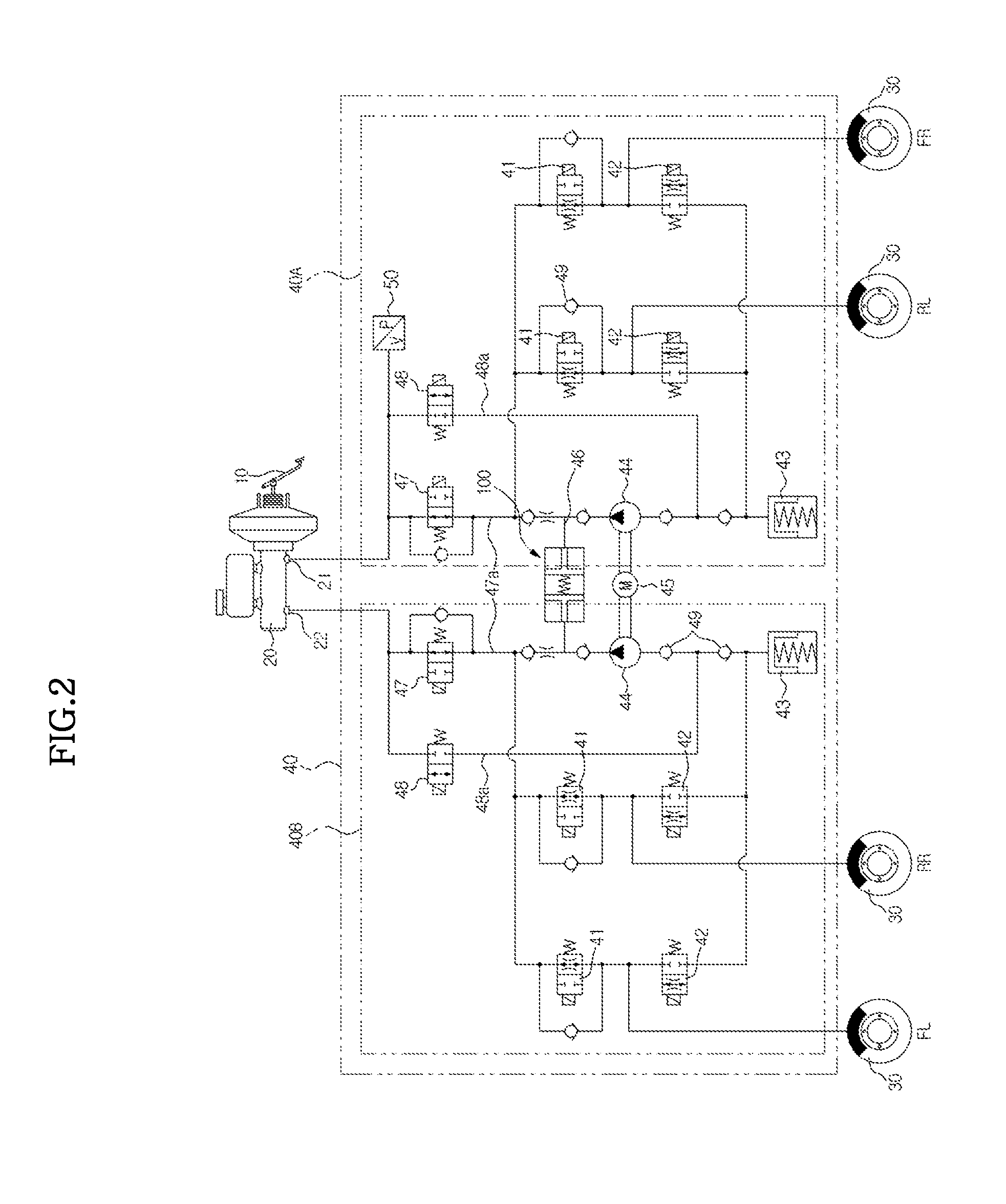
[0027]FIG. 2 is a diagram showing a brake system in which a pressure damping device according to a preferred embodiment of the present invention is provided.

[0028]Referring to FIG. 2, the brake system includes a brake pedal 10 that receives an operation force of a driver, a brake booster 11 that doubles a tread force using a pressure difference between ...


PUM


Abstract

There is provided a pressure damping device for a brake system. According to an embodiment of the present invention, an air damping space whose volume is changed in accordance with pressure is provided in an oil passage for connecting two hydraulic circuits, thereby reducing a pressure pulsation generated by a liquid pressure.

Description

CROSS-REFERENCE TO RELATED APPLICATION[0001]This application claims the benefit of Korean Patent Application No. 2012-0039834, filed on Apr. 17, 2012 in the Korean Intellectual Property Office, the disclosure of which is incorporated herein by reference.BACKGROUND[0002]1. Field[0003]Embodiments of the present invention relate to a pressure damping device for a brake system, and more particularly, to a pressure damping device for a brake system that may reduce noise and improve pedal feel by minimizing a pressure pulsation when braking.[0004]2. Description of the Related Art[0005]In general, a brake system for braking is essentially mounted to a vehicle, and in recent years, many kinds of systems to obtain more powerful and stable braking force have been proposed. Among these, in a hydraulic braking system, two hydraulic circuits are provided to control two wheels, and a pressure damping device for reducing a pressure pulsation is provided in an oil passage for connecting the two hyd...

Claims


Application Information

Patent Timeline
IPC IPC(8): B60T17/04
CPCB60T17/04B60T8/4068B60T8/4872F16L55/053B60T8/36B60T8/48F16L55/04
Inventor LEE, CHUNG JAE
Owner HL MANDO CORP
Why Eureka
Try Eureka