Rotary pump device and vehicle brake control system

a technology of rotary pump and brake control system, which is applied in the direction of positive displacement liquid engine, piston pump, liquid fuel engine, etc., can solve the problems of insufficient pushing force (pressure) applied to the pump body, deformation of the pump body casing, and increase of the gap between parts for forming the casing, so as to improve the durability of the casing and reduce the rigidity

Active Publication Date: 2011-05-19
ADVICS CO LTD
View PDF9 Cites 11 Cited by
  • Summary
  • Abstract
  • Description
  • Claims
  • Application Information

AI Technical Summary

Benefits of technology

[0031]According to the above feature (the second cylinder is firmly fixed to the housing), it is possible to apply the pushing force (pressure) of a desired value to the axial forward and backward end surfaces of the first pump casing, even when no spring is provided in the pump device or a spring having only a small spring force is provided in the pump device.
[0032]In addition, since the second cylinder is firmly fixed to the housing in the cylindrical recessed portion thereof, the fluid pressures different (independent) from each other, for example a minimum necessar...

Problems solved by technology

In other words, a surface area of the axial forward end of the pump body to which the high pressure is applied is rather small, and thereby only insufficient pushing force (pressure) may be applied t...

Method used


Image

  • Rotary pump device and vehicle brake control system
  • Rotary pump device and vehicle brake control system
  • Rotary pump device and vehicle brake control system

Examples


second embodiment

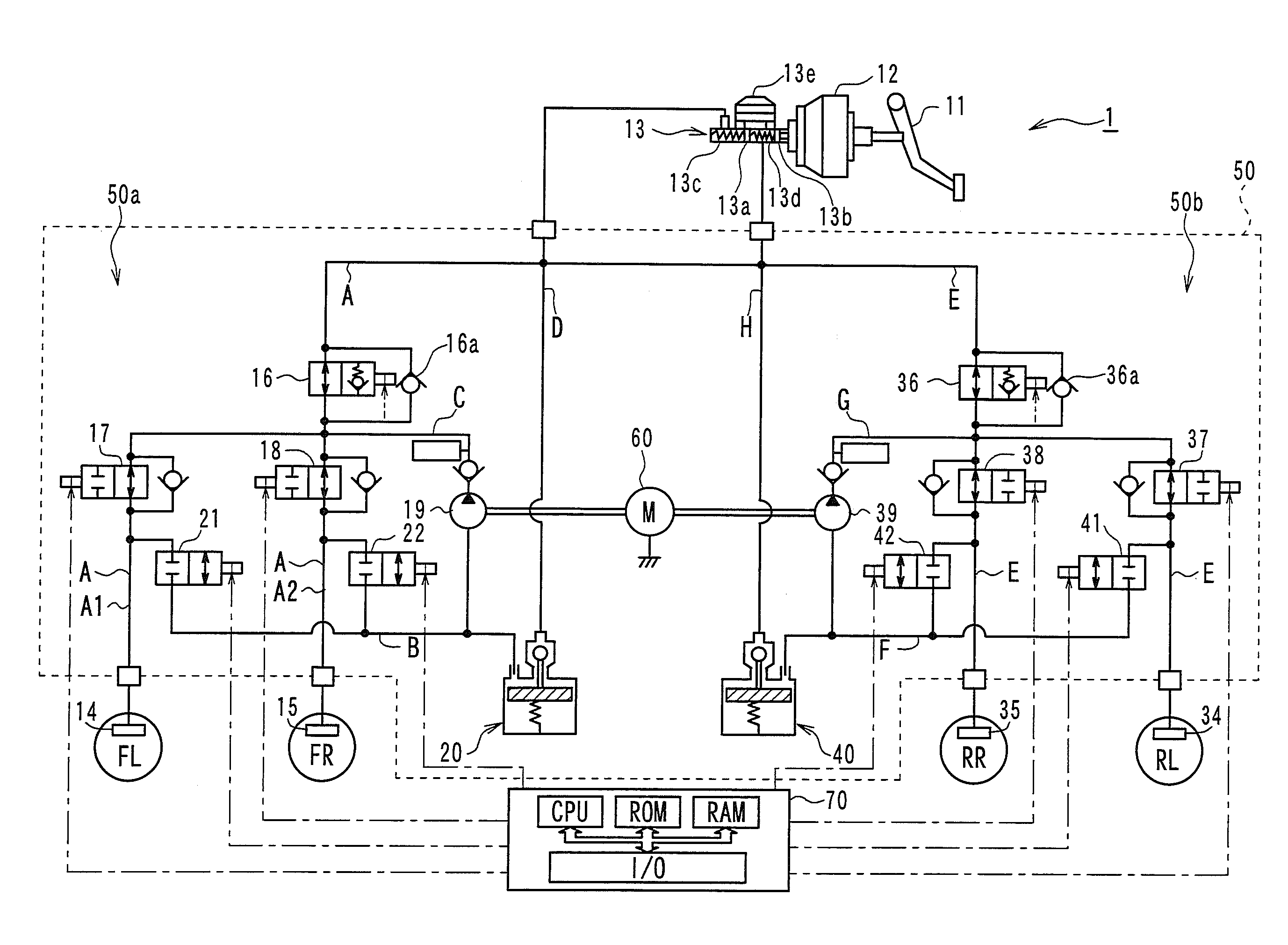
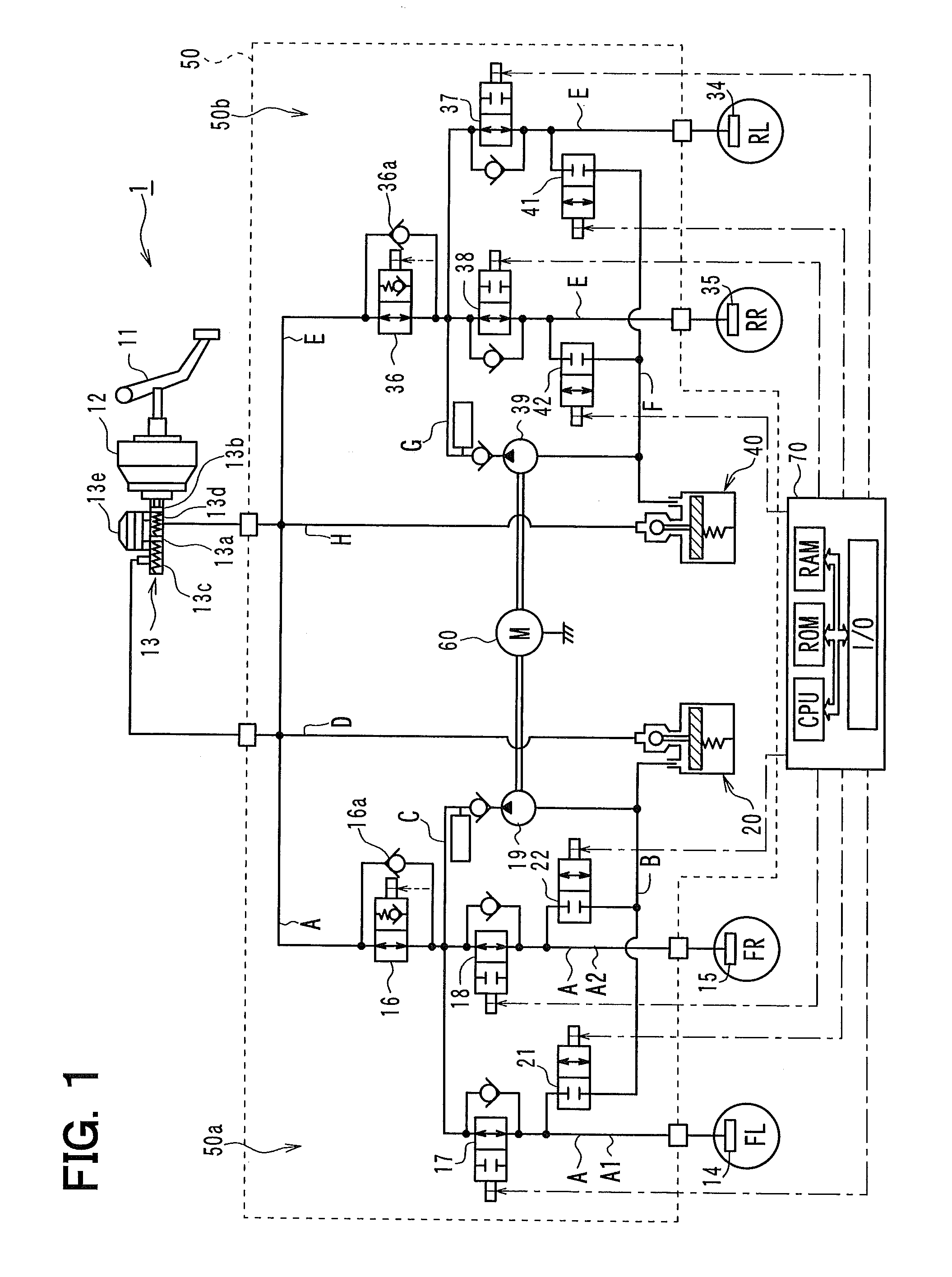
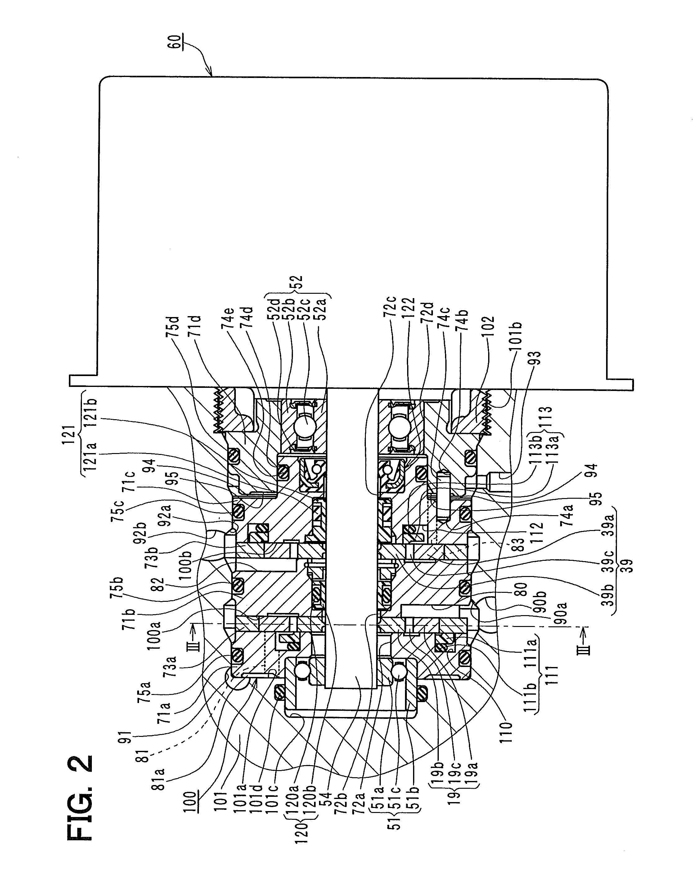
[0116]A second embodiment of the present invention will be explained. A vehicle brake control system, to which a rotary pump device according to the present embodiment is applied, is similar to the vehicle brake control system of the first embodiment. Namely, a part of the rotary pump device shown in FIG. 2 is modified. Such modified portions will be explained with reference to FIG. 2.

[0117]According to the rotary pump device of the second embodiment, the outer peripheral portion of the second cylinder 71b is fixed to the inner peripheral surface of the cylindrical recessed portion 101a of the housing 101 by means of adhesive material, press insertion, and so on. The other portions are the same to the first embodiment.

[0118]The rotary pump device of the above structure operates basically in the same manner to the first embodiment. Since the second cylinder 71b is firmly fixed to the housing 101, the first pump casing (which is composed of the first to third cylinders 71a to 71c as w...

third embodiment

[0126]A third embodiment of the present invention will be explained. According to the third embodiment, the vehicle brake control system (incorporating the rotary pump device) of the first embodiment is used but the first pump casing provided in the pump device is axially moved so as to increase pressure increase response for the wheel cylinder pressure. Since the basic structure for the vehicle brake control system and its pump device are the same to the first embodiment, a different point, that is a control method of the brake control system and the pump device, will be explained.

[0127]At an initial checking stage for starting a vehicle engine, a vehicle stopping stage, a stopping stage of the vehicle movement control and so on, an operation for increasing the brake fluid pressure at the wheel cylinders 14 and 15 of only the first hydraulic circuit 50a is carried out (this is achieved in the same manner to the first embodiment already explained above), so that the first pump casin...

fourth embodiment

[0134]A fourth embodiment of the present invention will be explained. In the above third embodiment, the first pump casing is moved to its backward position in the insertion direction, for example, at the initial checking stage for starting the vehicle engine. According to the fourth embodiment, the first pump casing is mechanically moved to its backward position in the insertion direction. The brake control system as well as the rotary pump device is basically the same to that of the first embodiment. Explanation is made for those portions, which are different from the first embodiment.

[0135]FIG. 6 is a schematic cross sectional view showing a pump body 100 of a rotary pump device, which is incorporated into a vehicle brake control system according to the fourth embodiment of the present invention.

[0136]As shown in FIG. 6, a return spring 200 is provided between the first cylinder 71a and the bottom surface of the cylindrical recessed portion 101a, which is different from the pump ...


PUM


Abstract

A first and a second rotary pumps are provided in a first pump casing of a pump body, which is inserted into a cylindrical recessed portion of a housing 101. A first outlet port is opened at a first space formed between a bottom surface of the cylindrical recessed portion and an axial forward end surface of the first pump casing, so that discharge pressure of working fluid of the first pump is supplied to the first space. A second outlet port is opened at a second space formed between an axial backward end surface of the first pump casing and an axial forward end surface of a second pump casing, so that discharge pressure of working fluid of the second pump is supplied to the second space.

Description

CROSS REFERENCE TO RELATED APPLICATION[0001]This application is based on Japanese Patent Application No. 2009-263864 filed on Nov. 19, 2009, the disclosure of which is incorporated herein by reference.FIELD OF THE INVENTION[0002]The present invention relates to a rotary pump device having an internal gear pump, such as a trochoid pump, and a vehicle brake control system incorporating the rotary pump device.BACKGROUND OF THE INVENTION[0003]A pump device of a rotary type for a vehicle brake control system is known in the art, for example, as disclosed in Japanese Patent Publication No. 2007-125929, according to which a force is generated by a spring member in an axial direction in order not only to restrict a movement of a pump body (in which rotary pumps for two hydraulic systems are accommodated) in the axial direction thereof but also to prevent a pump casing of the pump body from being damaged by internal pressure of brake fluid discharged from the rotary pumps at high pressure. I...

Claims


Application Information

Patent Timeline
IPC IPC(8): F04B25/00F04B35/04F04B53/00
CPCB60T8/4031F04C11/001F04C2/102B60T17/02
Inventor KAWABATA, TOMOAKIANDO, KUNIHITO
Owner ADVICS CO LTD
Why Eureka
Try Eureka