Method of controlling a cyclically commutated hydraulic pump

a hydraulic pump and cyclic commutation technology, applied in the direction of pump control, fluid couplings, positive displacement liquid engines, etc., can solve the problems of starting a full stroke pumping cycle, no longer available for additional pumping, and actually being problematic, so as to reduce pressure pulsation

Active Publication Date: 2012-06-05
ARTEMIS INTELLIGENT POWER
View PDF28 Cites 11 Cited by
  • Summary
  • Abstract
  • Description
  • Claims
  • Application Information

AI Technical Summary

Benefits of technology

[0018]It is therefore the object of the invention to provide a method for controlling a synthetically commutated hydraulic pump in a way that pressure pulsations can be decreased.
[0021]A preferred embodiment can be realised if the time evolvement function is able to trigger a pumping / motoring stroke for a plurality of working chambers and / or at a plurality of phases of each working chamber's working cycle. The pumping / motoring stroke is of course an active one. Previously, the decision of whether to initiate a pumping stroke or not, and about the displacement fraction to be chosen, was done slightly before the bottom dead centre of the respective cylinder and only for this single cylinder. According to this embodiment, it is not only suggested to trigger a pumping stroke (i.e. to make a decision about a pumping stroke) for more than one working chamber at a time, but also at several points during the working cycle of the respective working chamber(s). The decision can also be done during a continues time interval. This can increase the responsiveness of the pump and can decrease pressure pulses.
[0023]According to another embodiment of the invention, the time evolvement function comprises a vectorised variable, being indicative of the time dependency of the fluid output flow during a pumping stroke. In other words, for implementing the time evolvement function numerically, it is suggested to use a vectorial accumulator instead of a scalar accumulator. The decision of whether to initiate a pumping stroke or not can depend on one or on several fields of the vector. The update of the vectorised variable can comprise adding or subtracting a value to / from one or several fields. Furthermore, it can comprise a shifting of one or several fields of the vectorised variable. If more fields (“dimensions” or phases) are used for the vectorised variable, the accuracy and the time responsiveness of the pump can be enhanced. However, the enhancement can become negligible at some point. This point normally depends on the actual application. Furthermore, the workload of updating the vectorised variable can increase to an undesirable level. Therefore, a good compromise should be chosen for each individual application.
[0024]Another possible embodiment is achieved, if the time evolvement function comprises a variable being indicative of a fluid flow demand, wherein a threshold level of said variable is chosen in a way that a pumping / motoring stroke is initiated in advance of the actual demand. When using an accumulator, this could be realised by setting the threshold level to a level lower than the percentage of the pumping cycle that will be initiated. For example, an accumulator value of 50% could initiate a full stroke pumping cycle (100% stroke). This, of course, can imply, that the accumulator can have negative values. The threshold level can be chosen, depending on the demand, i.e. the slope of the accumulator. Using this embodiment, one might still suffer from certain imperfections. But it has the advantage, that it can be easily implemented with existing synthetically commutated hydraulic pumps.
[0025]It is preferred, if a plurality of electrically actuated valves are controlled using the suggested method. Particularly, the respective electrically actuated valves are connected to different working chambers of the fluid working machine. In this way, the advantages of the present invention will be even more predominant. In particular, the responsiveness of the pump can be increased, while the pressure pulses can be further decreased.

Problems solved by technology

This means, as a consequence, that a working chamber, being involved with a pumping cycle, is no longer available for additional pumping until the respective working cycle is completed.
Therefore, it may actually be problematic, to start a full stroke pumping cycle, because the respective cylinder will be blocked for a full revolution of the fluid working machine.
This could be, for example, a shutdown under critical working conditions, or a reduction in power, because there is a risk of engine overheating.

Method used


Image

  • Method of controlling a cyclically commutated hydraulic pump
  • Method of controlling a cyclically commutated hydraulic pump
  • Method of controlling a cyclically commutated hydraulic pump

Examples


Embodiment Construction

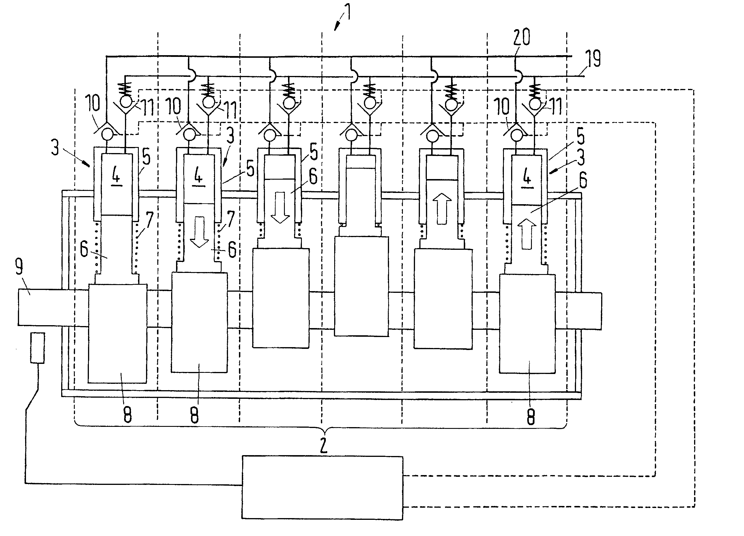
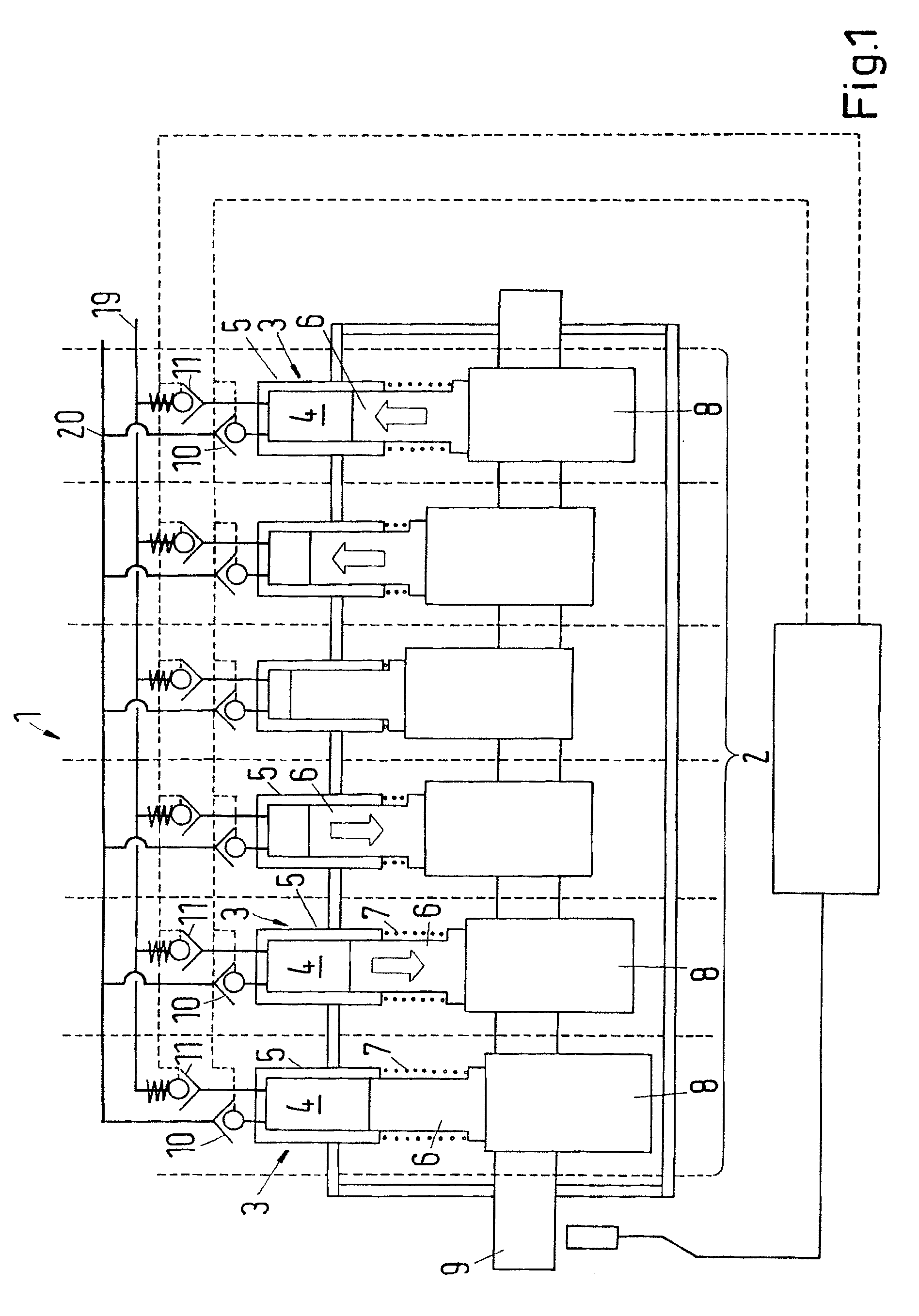
[0039]In FIG. 1, an example of a synthetically commutated hydraulic pump 1, with one bank 2, having six cylinders 3 is shown. Each cylinder has a working space 4 of a cyclically changing volume. The working spaces 4 are essentially defined by a cylinder part 5 and a piston 6. A spring 7 pushes the cylinder part 5 and the piston 6 apart from each other. The pistons 6 are supported by the eccentrics 8, which are attached off-centre of the rotating axis of the same rotatable shaft 9. In the case of a conventional radial piston pump (“wedding-cake”-pump), multiple pistons can also share the same eccentric 8. The orbiting movement of the eccentric 8 causes the pistons 6 to reciprocally move in and out of the respective cylinder parts 5. By this movement of the pistons 6 within the cylinder parts 5, the volume of the working spaces 4 is cyclically changing.

[0040]In the example shown in FIG. 1, the synthetically commutated hydraulic pump 1 is of a type with electrically actuated inlet valv...


PUM


Abstract

When employing synthetically commutated hydraulic pumps (1), a time delay between a change in fluid flow demand (15) and the resulting fluid flow output (13) can be observed. It is suggested to use a time evolvement function, taking into account the time evolvement of the fluid flow demand and / or the time evolvement of the pumping strokes, to modify the actuation of the electrically commutated valves.

Description

CROSS REFERENCE TO RELATED APPLICATION[0001]Applicant hereby claims foreign priority benefits under U.S.C. §119 from European Patent Application No. 07254332.5 filed on Nov. 1, 2007, the contents of which are incorporated by reference herein.FIELD OF THE INVENTION[0002]The invention relates to a method of operating a fluid working machine, comprising at least one working chamber of cyclically changing volume, a high pressure fluid connection, a low pressure fluid connection and at least one electrically actuated valve connecting said working chamber to said high pressure fluid connection and / or said low pressure fluid connection, wherein the pumping and / or motoring strokes of said working chamber are controlled by an appropriate actuation of said electrically actuated valve. The invention further relates to a fluid working machine, comprising at least one working chamber of cyclically changing volume, a high pressure fluid connection, a low pressure fluid connection, at least one el...

Claims


Application Information

Patent Timeline
Patent Type & Authority Patents(United States)
IPC IPC(8): F16D31/02
CPCF04B7/0076F04B49/065F04B49/22
Inventor KUTTLER, ONNOLAI, KEN KIN-HO
Owner ARTEMIS INTELLIGENT POWER
Why Eureka
Try Eureka