Hydraulic brake system

a brake system and hydraulic technology, applied in the direction of brake systems, brake components, brake cylinders, etc., can solve the problems of increasing the manufacturing cost of the brake, reducing the performance and complicated passage structure, so as to achieve the effect of reducing the pressure pulsation

Active Publication Date: 2015-12-17
HL MANDO CORP
View PDF12 Cites 11 Cited by
  • Summary
  • Abstract
  • Description
  • Claims
  • Application Information

AI Technical Summary

Benefits of technology

[0010]Therefore, it is an aspect of the present disclosure to provide a hydraulic brake system capable of ensuring easy production thereof by disposing the inlet port a...

Problems solved by technology

However, a plurality of passages formed in a modulator block to control a braking pressure are configured such that a plurality of solenoid valves, pumps, low pressure accumulators and high pressure accumulators are connected at an inside of the modulator block, which complicates the structure of the passages and causes difficulty in disposing the inlet port and the outlet port connected to the...

Method used


Image

  • Hydraulic brake system
  • Hydraulic brake system
  • Hydraulic brake system

Examples


Embodiment Construction

[0028]Various embodiments will now be described more fully with reference to the accompanying drawings in which some embodiments are shown. These inventive concepts may, however, be embodied in different forms and should not be construed as limited to the embodiments set forth herein. Rather, these embodiments are provided so that this disclosure is thorough and complete and fully conveys the inventive concept to those skilled in the art. In the drawings, the sizes and relative sizes of layers and regions may be exaggerated for clarity.

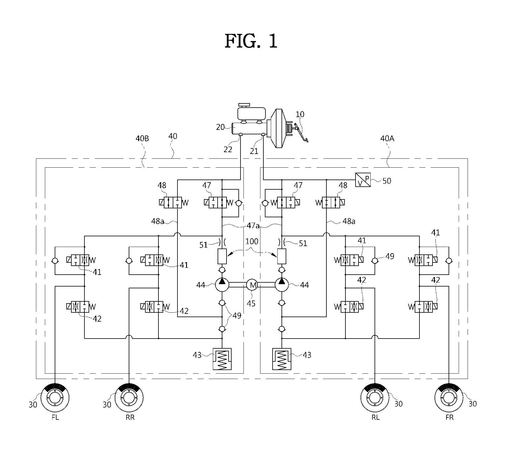
[0029]FIG. 1 is a hydraulic circuit diagram of a hydraulic brake system according to an embodiment of the present disclosure.

[0030]Referring to FIG. 1, a hydraulic brake system according to an embodiment of the present disclosure includes a brake pedal 10 that receives an operation force of a driver, a brake booster 11 that amplifies a tread force by using difference between the vacuum pressure and the atmospheric pressure by the tread force, a master...


PUM


Abstract

Disclosed is a hydraulic brake system provided with a high pressure accumulator that reduces a pressure pulsation of brake oil being discharged through operation of a pump. The high pressure accumulator includes a damping member that is provided in a bore communicating with an inlet port and an outlet port of the high pressure accumulator respectively allowing brake oil to be introduced and discharged therethrough, and is provided with a bypass flow passage connecting the inlet port to the outlet port, and a reinforcing member installed at the damping member to improve durability of the damping member.

Description

CROSS-REFERENCE TO RELATED APPLICATION[0001]This application claims the benefit of Korean Patent Application No. 2014-0071883, filed on Jun. 13, 2014 in the Korean Intellectual Property Office, the disclosure of which is incorporated herein by reference.BACKGROUND[0002]1. Field[0003]Embodiments of the present disclosure relate to a hydraulic brake system, and more particularly, to a hydraulic brake system capable of reducing a pressure pulsation of brake oil discharged from a pump.[0004]2. Description of the Related Art[0005]In general, a hydraulic brake system includes a modulator block provided with a plurality of solenoid valves, a low pressure accumulator that temporarily stores oil and a high pressure accumulator, a pump that pumps oil stored in the low pressure accumulator and a motor that drives the pump, and an electronic control unit (ECU) that controls electrically operated parts, thereby controlling braking pressure transmitted to brakes of a vehicle.[0006]The hydraulic b...

Claims


Application Information

Patent Timeline
IPC IPC(8): B60T13/14
CPCB60T13/14B60T13/148B60T13/12B60T8/4068B60T8/4872B60T8/40B60T8/42
Inventor DOH, YOON-HO
Owner HL MANDO CORP
Why Eureka
Try Eureka