Burner comprising a fluidic oscillator, for a gas turbine, and a gas turbine comprising at least one such burner

a technology of fluid oscillator and burner, which is applied in the direction of burners, combustion processes, lighting and heating apparatus, etc., can solve the problems of increasing the risk of pressure pulsation, and achieve the effect of reducing pollution emissions and reducing pressure pulsations

Inactive Publication Date: 2017-09-07
SIEMENS AG
View PDF0 Cites 11 Cited by
  • Summary
  • Abstract
  • Description
  • Claims
  • Application Information

AI Technical Summary

Benefits of technology

[0010]It is an object of the present invention to provide a burner of the type mentioned in the introduction for a gas turbine, with which reduction of pollution emissions or reduction of pressure pulsations is made possible during operation of the burner.

Problems solved by technology

In particular, although premix burners have low pollution emissions during operation, they are however more susceptible to the formation of pressure pulsations.

Method used


Image

  • Burner comprising a fluidic oscillator, for a gas turbine, and a gas turbine comprising at least one such burner
  • Burner comprising a fluidic oscillator, for a gas turbine, and a gas turbine comprising at least one such burner
  • Burner comprising a fluidic oscillator, for a gas turbine, and a gas turbine comprising at least one such burner

Examples


Embodiment Construction

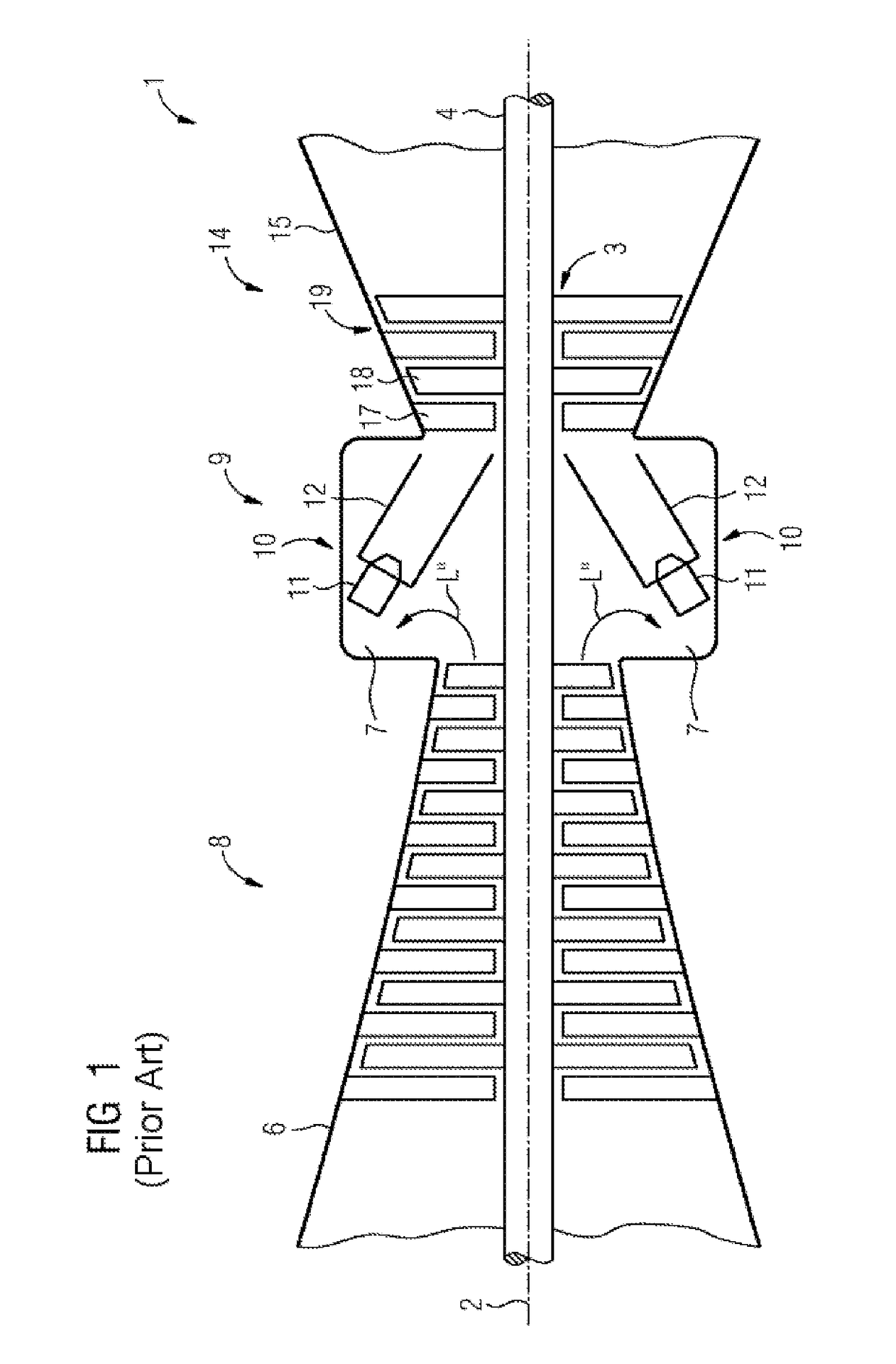
[0057]FIG. 1 shows a sectional view of a gas turbine 1 according to the prior art in a schematically simplified representation. The gas turbine 1 internally comprises a rotor 3 which is mounted so as to rotate about a rotation axis 2, has a shaft 4 is also referred to as the turbine rotor. Successively along the rotor 3, there are an intake manifold 6, a compressor 8, a combustion system 9 having a number of combustion chambers 10, each of which comprises a burner arrangement having burners 11, a fuel supply system (not represented) for the burners and a housing 12, a turbine 14 and an exhaust manifold 15. The combustion chamber 10 may, for example, be a ring combustion chamber. The gas turbine could however also comprise tube combustion chambers, which are for example arranged annularly at the turbine entry.

[0058]The combustion system 9 communicates with an e.g. annular hot-gas channel. There, a plurality of turbine stages connected in series form the turbine 14. Each turbine stage...


PUM


Abstract

A burner having a pre-mixing passage delimited radially outwardly by a wall, a burner lance and a plurality of fuel injectors arranged in the pre-mixing passage, the injectors extending from the burner lance in the direction of the wall and having fuel nozzles. The fuel supply arrangement has at least one fluidic oscillator that has an interaction chamber, an inlet to the interaction chamber connected to a fuel channel of the fuel supply arrangement, a first outlet channel of the interaction chamber extending at least to a first fuel nozzle and a second outlet channel extending at least to a second fuel nozzle, the fluidic oscillator has one feedback line for each outlet channel, one end of the feedback line terminating into the respective outlet channel downstream of the at least one fuel nozzle, and the other end thereof terminating into an inlet region of the interaction chamber.

Description

CROSS REFERENCE TO RELATED APPLICATIONS[0001]This application is the US National Stage of International Application No. PCT / EP2015 / 070355 filed Sep. 7, 2015, and claims the benefit thereof. The International Application claims the benefit of German Application No. DE 102014218288.3 filed Sep. 12, 2014. All of the applications are incorporated by reference herein in their entirety.FIELD OF INVENTION[0002]The invention relates to a burner for a gas turbine, having a central burner axis and a premix passage enclosing the burner axis at least in sections. The premix passage therefore has a passage cross-sectional area which extends around the burner axis. The central burner axis is an infinitely long imaginary line. The passage cross-sectional area may, for example, be arranged around the burner axis annularly or as a full circle. In other words, the premix passage may extend coaxially with the burner axis (same rotation axis). The diameter of the ring or full circle may vary along the ...

Claims


Application Information

Patent Timeline
Patent Type & Authority Applications(United States)
IPC IPC(8): F23R3/28F23D11/36
CPCF23D11/36F23R3/286F23C2900/07001F23R3/20F23R2900/00014
Inventor BOTTCHER, ANDREASDEISS, OLGAGRIEB, THOMASHASE, MATTHIASKREBS, WERNERLAPP, PATRICKPFADLER, SEBASTIANVOGTMANN, DANIEL
Owner SIEMENS AG
Why Eureka
Try Eureka