High-pressure fuel pressure accumulator

A high-pressure fuel and pressure accumulator technology, applied in fuel injection devices, special fuel injection devices, charging systems, etc., can solve manufacturing difficulties, difficult common rail 100 manufacturing standardization, and difficult mass production of various types of common rails 100 and other questions

Inactive Publication Date: 2004-08-04
DENSO CORP
View PDF1 Cites 11 Cited by
  • Summary
  • Abstract
  • Description
  • Claims
  • Application Information

AI Technical Summary

Problems solved by technology

[0004] according to Figure 8 As shown in the structure, since the throttle valve 120 is located at the bottom of the pipe joint 110 connected with the high-pressure pipe 130, it is a difficult work to manufacture the throttle valve 120, and it is difficult to make the throttle valve 120 with precise dimensions, lead to higher manufacturing costs
[0005] Also, since the throttle valve 120 is directly formed on the main body of the common rail 100, it is difficult to mass-produce various models of the common rail 100, each of which has substantially the same main body but has a throttle valve of a different diameter.
That is, it is difficult to standardize the manufacture of the common rail 100, resulting in higher production costs for high-pressure fuel accumulators

Method used


Image

  • High-pressure fuel pressure accumulator
  • High-pressure fuel pressure accumulator
  • High-pressure fuel pressure accumulator

Examples


no. 1 example

[0030] A high-pressure fuel accumulator according to the first embodiment of the present invention will be referred to Figure 1 to Figure 5 To describe, the high-pressure fuel accumulator is used in an accumulator-type fuel injection system for a four-cylinder diesel engine.

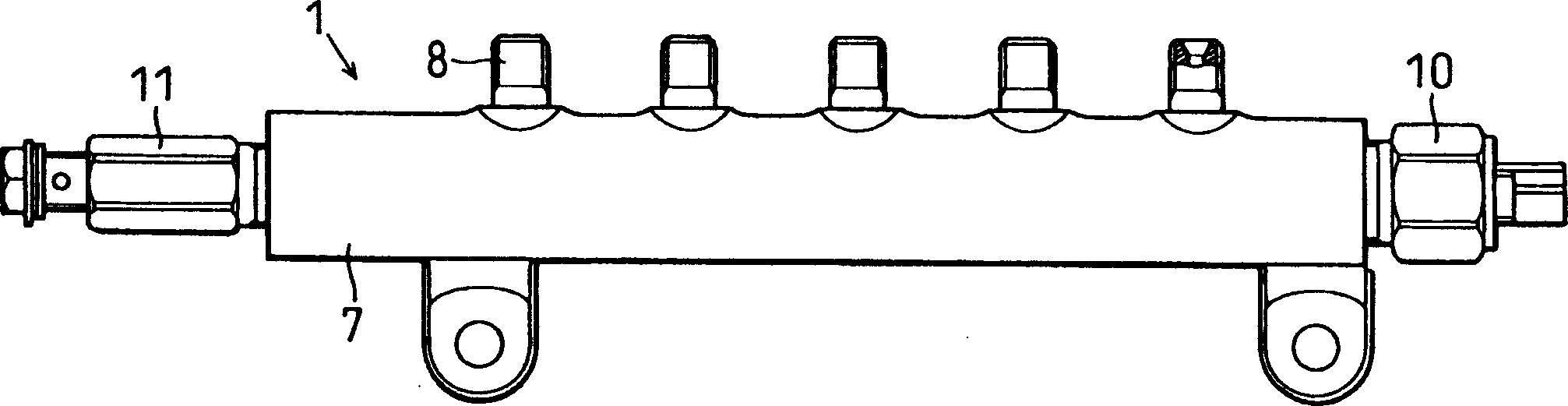
[0031] like image 3 As shown, the accumulator-type fuel injection system has a common rail 1, a high-pressure pump 3 for sucking fuel from a fuel tank 2 and pressurizing it and then discharging high-pressure fuel to the common rail 1, and a high-pressure pump 3 for pumping Fuel distribution pipe) 4 injector 5 that injects high-pressure fuel from the common rail to each cylinder of the diesel engine, and ECU (Electronic Control Unit) 6 used to control the system itself. The common rail 1 and the high-pressure pipe 4 constitute a high-pressure fuel accumulator.

[0032] like figure 2 As shown, the common rail 1 includes a pressure accumulator pipe (main body) 7 in which high-pressure fuel is accumula...

no. 2 example

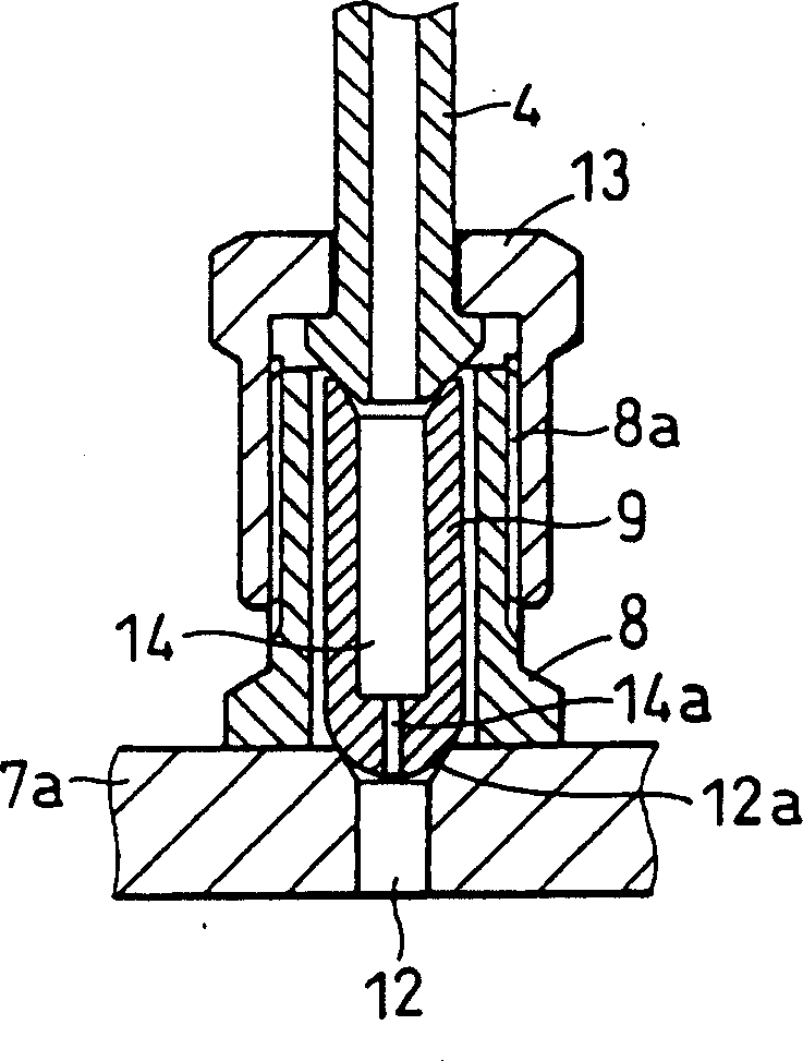
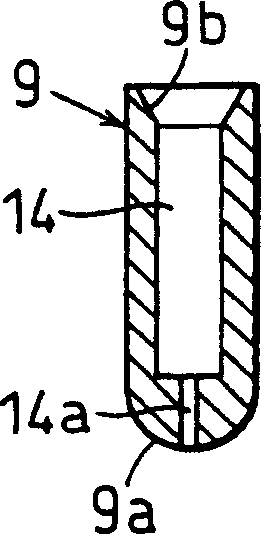
[0048] In the high-pressure fuel accumulator according to the second embodiment, as Image 6 As shown, the seating surface 9b of the orifice member 9 is positioned above the axially upper end of the pipe joint 8 .

[0049] Even in the case where the outer diameter of the orifice member is small due to the relatively small thread diameter of the pipe joint, it is necessary to make the seating surface 9b of the orifice member 9 sufficiently large in area to be able to face the surface of the high-pressure pipe 4a. Block. To this end, the axial end of the orifice member 9 on the opposite side of the orifice 14a is positioned above the axial upper end of the pipe joint 8 and has a flange 9c forming a seating surface 9b therein.

[0050] With this structure, even if the thread diameter of the pipe joint 8 is smaller than that of the first embodiment, the orifice member 9 has a sufficiently large seating surface 9b for ensuring reliable sealing.

no. 3 example

[0052] In the high-pressure fuel accumulator according to the third embodiment, as Figure 7 As shown, the pipe joint 8 and the pressure accumulator pipe 7 are integrated into a single piece. In the third embodiment, the orifice 14a is formed in the orifice member 9 inserted into the inside of the pipe fitting 8, and this embodiment has the same advantages as the first embodiment. However, the third embodiment is inferior to the first embodiment in terms of standardization of manufacture of the common rail 1 because the pipe joint 8 is integrated with the pressure accumulator pipe 7 .


PUM


Abstract

A common rail has an accumulation pipe in which high pressure fuel is accumulated, a pipe joint to which a high pressure pipe is connected and an orifice member housed inside the pipe joint. The orifice member is provided with a conduit through which a fuel port formed in the accumulation pipe communicates with the high pressure pipe. The conduit is provided at an end thereof with an orifice. The orifice serves to reduce pressure pulsation generated by fuel injection of an injector so that fuel pressure in the common rail is stable. Since the orifice is formed in the orifice member housed in the pipe joint, the orifice is easily and accurately manufactured at a lower cost, compared to an orifice formed in the accumulation pipe. It is easy to standardize the manufacture of plural models of common rails whose orifice diameters are different.

Description

technical field [0001] The invention relates to a pipe joint structure of a high-pressure fuel pressure accumulator, and the pressure accumulator can be applied to a pressure-accumulating fuel injection system. Background technique [0002] There is conventionally known an accumulation type fuel injection system in which high-pressure fuel is accumulated in an accumulator called a common rail, and the accumulated high-pressure fuel is injected from each injector to each cylinder of a diesel engine. The conventional accumulator-type fuel injection system has the disadvantage that since the pressure of the fuel accumulated in the common rail is very high (for example, about 150 MPa), if a pressure pulsation occurs when fuel is injected from one of the injectors, the pressure pulsation may As a result, pressure changes in the common rail cause fluctuations in the fuel injection quantity and injection timing of other injectors. [0003] In order to overcome this shortcoming, as...

Claims


Application Information

Patent Timeline
Patent Type & Authority Applications(China)
IPC IPC(8): F02M55/00F02M55/02F02M63/00F02M63/02
CPCF02M2200/315F02M63/02F02M55/025F02M55/005
Inventor 近藤淳
Owner DENSO CORP
Why Eureka
Try Eureka