
Method and device for underwater recovery of products or pollutants

Active Publication Date: 2013-10-17
ALLEN DANA R
View PDF0 Cites 21 Cited by
  • Summary
  • Abstract
  • Description
  • Claims
  • Application Information

AI Technical Summary

Benefits of technology

The present invention has the advantage of being able to recover oil and gas leaks using multiple methods simultaneously. It can use affordable materials for most of the conduit, and can capture the entire leak or multiple leaks using multiple suction nozzles. It also delays or reduces the pressure aspect of clamping a blown out oil / natural gas well, which allows for the use of lightweight and inexpensive materials. The system can be ready for deployment quickly and does not require excessive customization. It also eliminates or reduces the need for dangerous chemical dispersants, reduces the danger of a second blowout, and is low in stress even at great depths. The recovery conduit can also be placed down-current from a leak, where it can be held in position by stays and cables.

Problems solved by technology

Current methods and equipment can be very expensive, labor intensive, and time-consuming to provide damage.
The consequences of any oil spill can be environmentally and economically disastrous, especially when an underwater solution does not exist and the spill continues to occur.
If the seafloor is compromised by fractures near oil reserves or if wellhead or pipeline equipment is severely damaged it is extremely difficult to capture the oil / natural gas at the source.
Alternatively, if an oil spill is partially captured at the water surface, the cost can be exorbitant, and the effectiveness and thoroughness is meager.

Method used


Image

  • Method and device for underwater recovery of products or pollutants
  • Method and device for underwater recovery of products or pollutants
  • Method and device for underwater recovery of products or pollutants

Examples


Embodiment Construction

[0021]Reference will now be made in detail to the preferred embodiments in the present disclosure. Examples of the preferred embodiment are illustrated in the accompanying drawings. While the present disclosure will be described in conjunction with the preferred embodiments, it is understood that they are not intended to limit the invention to these embodiments. Rather, the invention is intended to cover alternatives, modifications and equivalents, which may be included within the spirit and scope of the invention, as defined by the appended claims. Additionally, in the following detailed description of the present disclosure, numerous specific details are set forth in order to provide a thorough understanding of the present disclosure. However, it will be apparent to one of ordinary skill in the art that the present disclosure may be practiced without these specific details. In other instances, well-known methods, procedures, and components have not been described in detail so as n...


PUM

PropertyMeasurementUnit
Pressureaaaaaaaaaa
Flow rateaaaaaaaaaa
Flexibilityaaaaaaaaaa

Abstract

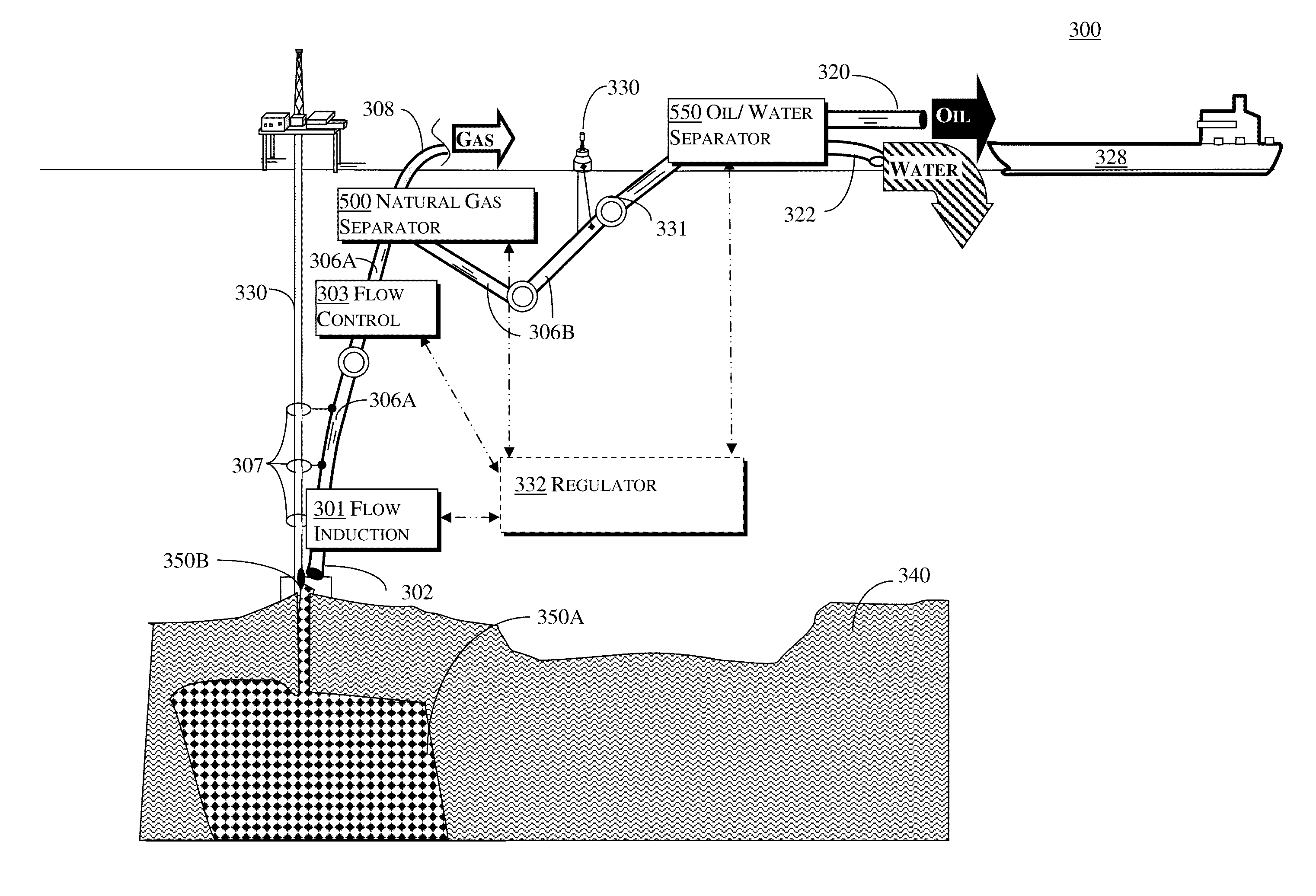
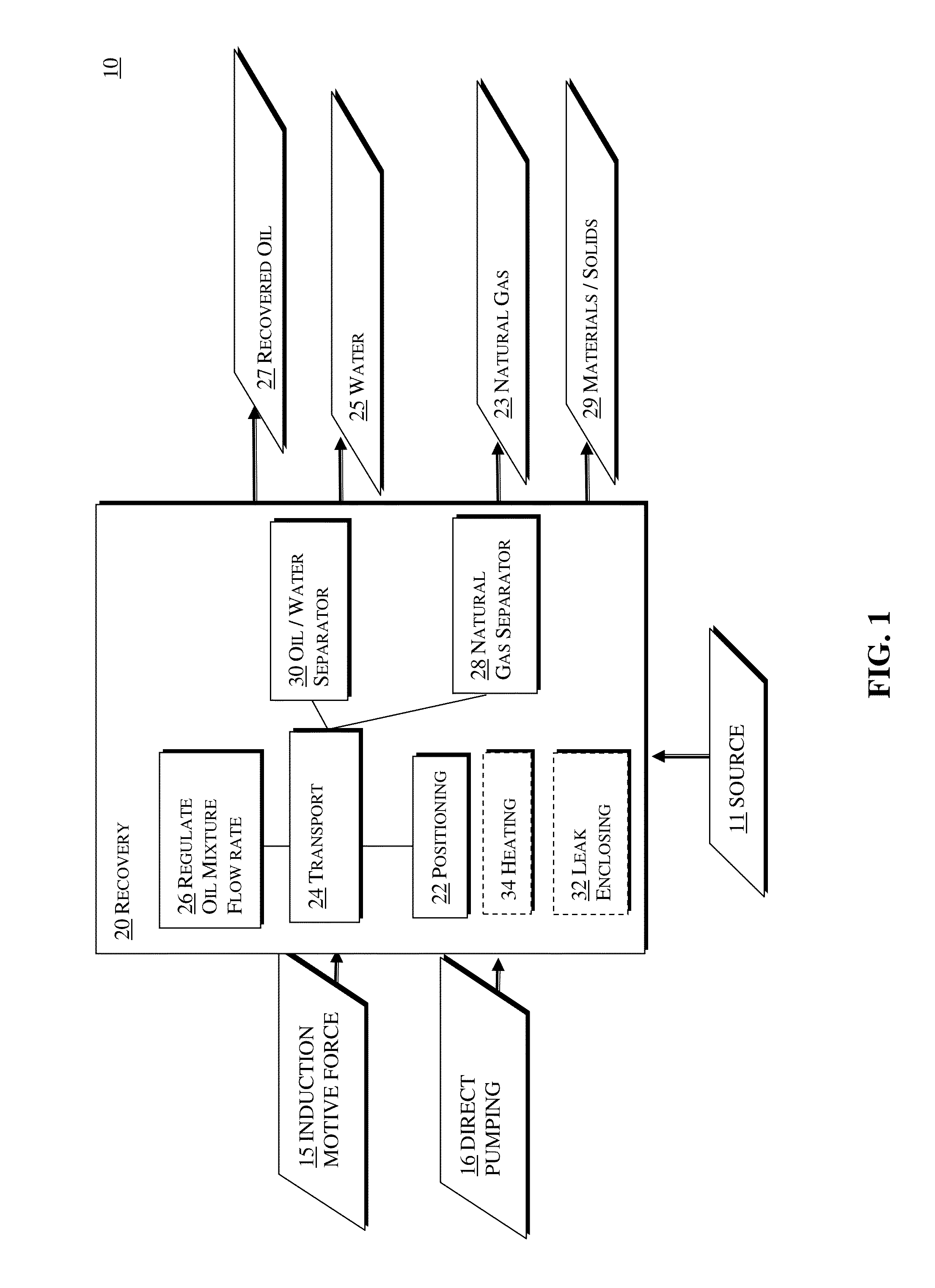
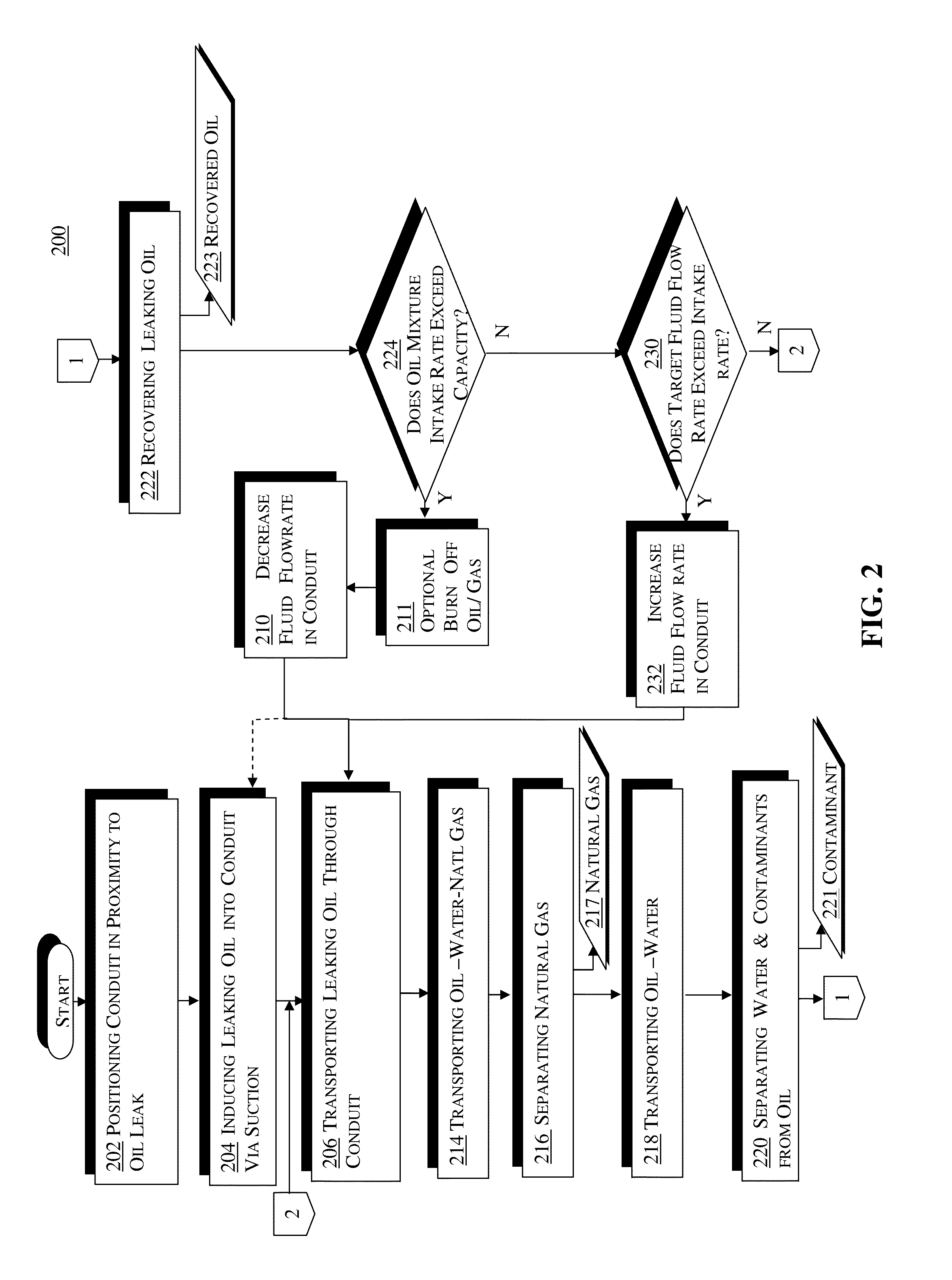
An apparatus, method, and system for recovering oil from a submerged oil source, wherein the system includes a submerged conduit having at least two openings, with a first opening capable of being located in proximity of a leak in order to capture leaking oil, and with a second opening capable of communicating captured leaking oil to another location. A natural gas separator, coupled to the submerged conduit separates the boiling vapor phase natural gas from the captured oil thereby outputting oil with water contaminant. An oil / water separator coupled to the natural gas separator then separates out the contaminant water, resulting in a processed recovered oil product for storage and subsequent refinement. The flow to capture the leak is induced by generating a lower pressure at nozzle in the conduit via power jet, air lift, pumping of fluid out of conduit close to sea level, or other methods. Flow within conduit can become self-propelled if natural gas is present and creates an “air lift” effect as the natural gas expands at lower pressures closer towards sea level.

Description

REFERENCE TO RELATED APPLICATIONS[0001]This application claims priority to provisional application Ser. No. 61 / 361,380, filed Jul. 3, 2010, entitled: “A METHOD AND DEVICE FOR UNDERWATER RECOVERY OF PRODUCTS OR POLLUTANTS,” which application is also incorporated herein by its reference, in its entirety.FIELD OF THE INVENTION[0002]The present disclosure relates generally to the field of underwater recovery and in particular to the field of recovering submerged objects, materials or fluids.DESCRIPTION OF THE RELATED ART[0003]Land-based wells for petroleum products such as crude oil, natural gas, etc. (“oil”) have been exploited for decades to seek the easiest and most productive sources. As national and world demand for oil has continued to rise, and as land-based sources have become insufficient, attention has been turned to other locations for petroleum reserves such as underwater, or submerged, wells in existence as early as the late-1800s.[0004]If an uncontrolled rupture, discharge...

Claims


Application Information

Patent Timeline
IPC IPC(8): B67D99/00E02F5/00
CPCB67D99/00E02F5/006E02F3/905E02F7/005E02F7/065E21B43/0122Y10S210/923C02F1/40E02B15/04E02F3/8858
Inventor ALLEN, DANA R.
Owner ALLEN DANA R
Learn More