
Systems and methods configured to estimate receiver position using timing data associated with reference locations in three-dimensional space

a three-dimensional space and receiver technology, applied in direction finders, instruments, measurement devices, etc., can solve the problems of device power consumption, difficult to determine the exact location of a mobile subscriber, and limitations of the system

Inactive Publication Date: 2013-10-17
NEXTNAV
View PDF9 Cites 67 Cited by
  • Summary
  • Abstract
  • Description
  • Claims
  • Application Information

AI Technical Summary

Benefits of technology

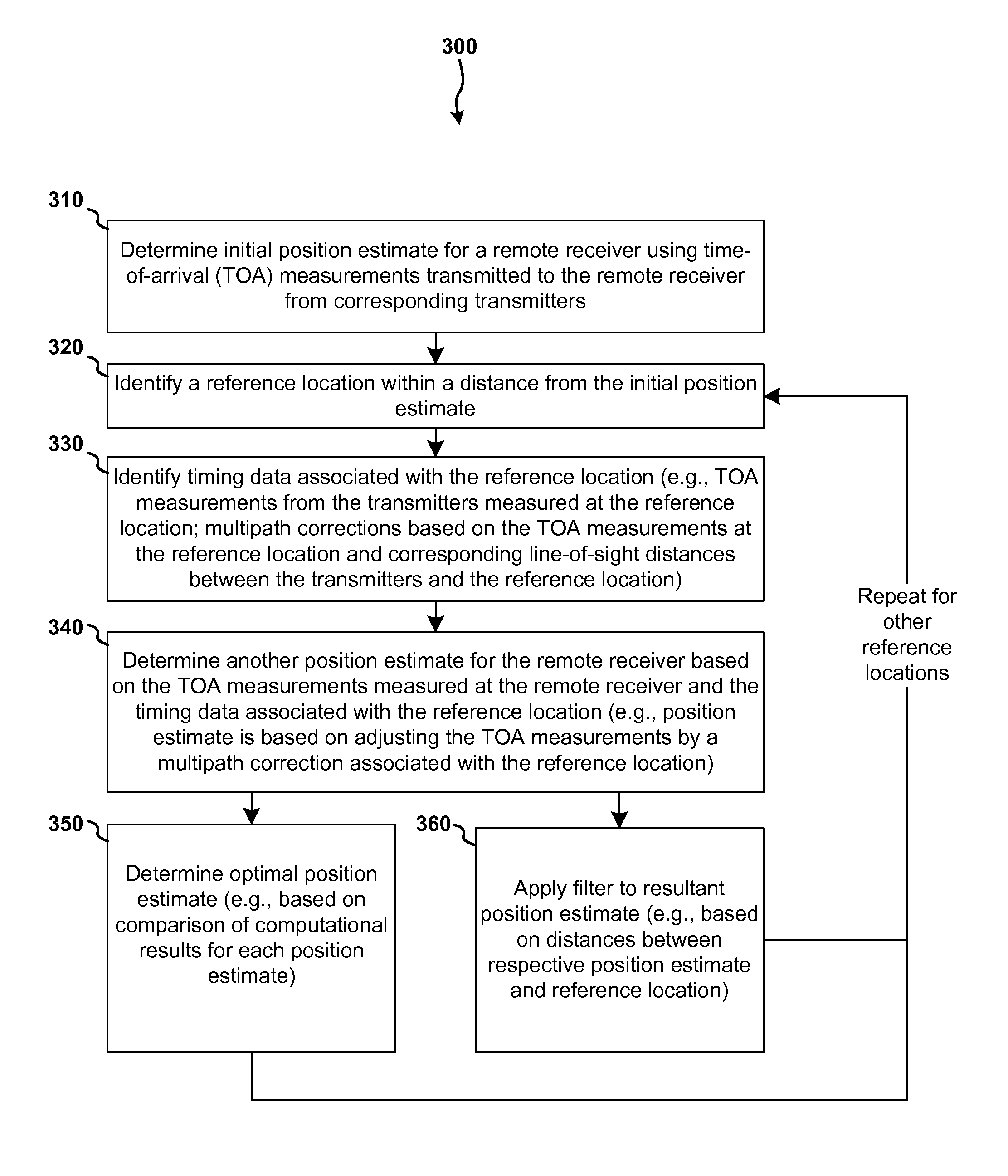
This patent describes a system, method, and computer program for determining the position of a remote receiver based on time-of-arrival measurements and associated timing data from transmitters. The system can use one or more reference locations within a predefined distance of the receiver to better estimate its position. The method includes steps for determining an initial position estimate, identifying timing data associated with the transmitters and the reference locations, and using the timing data to determine the initial position estimate. The system can also make use of multiple sets of time corrections to improve accuracy. The technical effect of the patent is to provide a more efficient and accurate way to locate remote receivers based on time-of-arrival measurements.

Problems solved by technology

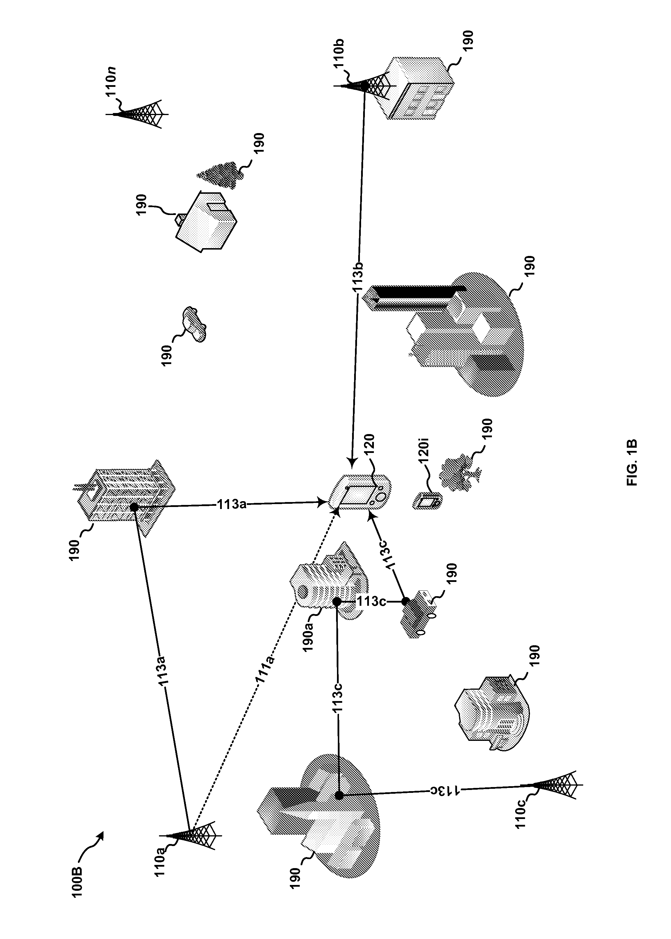
These systems do, however, have limitations associated with factors such as location accuracy, transmitted and received signal levels, radio channel interference and / or channel problems such as multipath, device power consumption, and the like.
Determination of a mobile subscriber's exact location can be quite challenging.
If the subscriber is indoors or in an urban area with obstructions, the subscriber's mobile device may not be able to receive signals from GPS satellites and the network may be forced to rely on network-based triangulation / multilateration methods that are less precise.
Additionally, if the subscriber is in a multi-story building, knowing only that the subscriber is in the building and not what floor they are on, will result in delays in providing emergency assistance (which could be potentially life-threatening).

Method used


Image

  • Systems and methods configured to estimate receiver position using timing data associated with reference locations in three-dimensional space
  • Systems and methods configured to estimate receiver position using timing data associated with reference locations in three-dimensional space
  • Systems and methods configured to estimate receiver position using timing data associated with reference locations in three-dimensional space

Examples


Embodiment Construction

[0024]Various aspects of the invention are described below. It should be apparent that the teachings herein may be embodied in a wide variety of forms and that any specific structure, function, or both, being disclosed herein is merely representative. Based on the teachings herein one skilled in the art should appreciate that any aspect disclosed may be implemented independently of any other aspects and that two or more of these aspects may be combined in various ways. For example, a system may be implemented or a method may be practiced using any number of the aspects set forth herein.

[0025]As used herein, the term “exemplary” means serving as an example, instance or illustration. Any aspect and / or embodiment described herein as “exemplary” is not necessarily to be construed as preferred or advantageous over other aspects and / or embodiments.

[0026]In the following description, numerous specific details are introduced to provide a thorough understanding of, and enabling description f...


PUM


Abstract

Systems, methods and computer program products for determining a position location estimate for a remote receiver based on one or more time-of-arrival measurements transmitted from one or more transmitters and first timing data associated with the one or more transmitters and further associated with one or more reference locations within a reference area of the remote receiver are described.

Description

CROSS-REFERENCE TO RELATED APPLICATIONS[0001]This application claims priority under 35 U.S.C. §119(e) to co-pending U.S. Provisional Patent Application Ser. No. 61 / 625,610, filed Apr. 17, 2012, entitled THREE DIMENSIONAL DIGITAL CITY MODEL-BASED RANGE MEASUREMENT ERROR MITIGATION FOR TERRESTRIAL TIME-OF-ARRIVAL WIRELESS POSITIONING SYSTEM, the content of which is hereby incorporated by reference herein in its entirety for all purposes.FIELD[0002]This disclosure relates generally to positioning systems. More specifically, but not exclusively, the disclosure relates to systems, methods, and computer program products for estimating receiver position using timing data associated with reference locations in three-dimensional space.BACKGROUND OF THE INVENTION[0003]Systems for providing position information are known in the art. For example, radio-bases systems such as LORAN, GPS, GLONASS, and the like have been used to provide position information for persons, vehicles, equipment, and the...

Claims


Application Information

Patent Timeline
IPC IPC(8): G01S5/02
CPCG01S5/02G01S5/009G01S5/0236G01S5/14G01S19/22G01S19/41G01S5/10
Inventor SENDONARIS, ANDREWKRASNER, NORMAN F.TANG, HAOCHEN
Owner NEXTNAV
Learn More