Illumination module

Inactive Publication Date: 2013-10-17
RADIANT OPTO ELECTRONICS
View PDF4 Cites 2 Cited by
  • Summary
  • Abstract
  • Description
  • Claims
  • Application Information

AI Technical Summary

Benefits of technology

[0035]The light-emitting materials of the illumination module of the present invention do not contact the light sources for preventing the photo-conversion efficiency from being affected by the heat generated from the light sources.
[0036]Furthermore, the illumination module may use a light guide element to converge the light-emitting regions of the light sources and to effectively guide the light to a fluorescence member, thereby decreasing the volume of the fluorescence member, thus decreasing the usage amount of the light-emitting materials, further decreasin

Problems solved by technology

However, the tungsten lamp or the fluorescent lamp has the disadvantages of large power consumption, less illumination efficacy and more heat generating, and thus the conventional light source does not meet the development tendency of modern lighting technologies and environmental requirements.
However, the light-emitting spectrum and intensity of the LEDs are often affected by the distribution of packaging materials including LED chips and phosphor, thus causing the illumination module easily to have non-uniform light color or brightness due to the differences among light-emitting spectrum or intensities of the LEDs.
However, the large amount of LEDs will increase the volume of the illumination module, and thus the illum

Method used


Image

  • Illumination module
  • Illumination module
  • Illumination module

Examples


Example

[0041]In the following description, several specific details are presented to provide a thorough understanding of the device structures according to embodiments of the present invention. One skilled in the relevant art will recognize, however, that the embodiments of the present invention provide many applicable inventive concepts which can be practiced in various specific contents. The specific embodiments discussed hereinafter are used for explaining but not limited of the scope of the present invention.

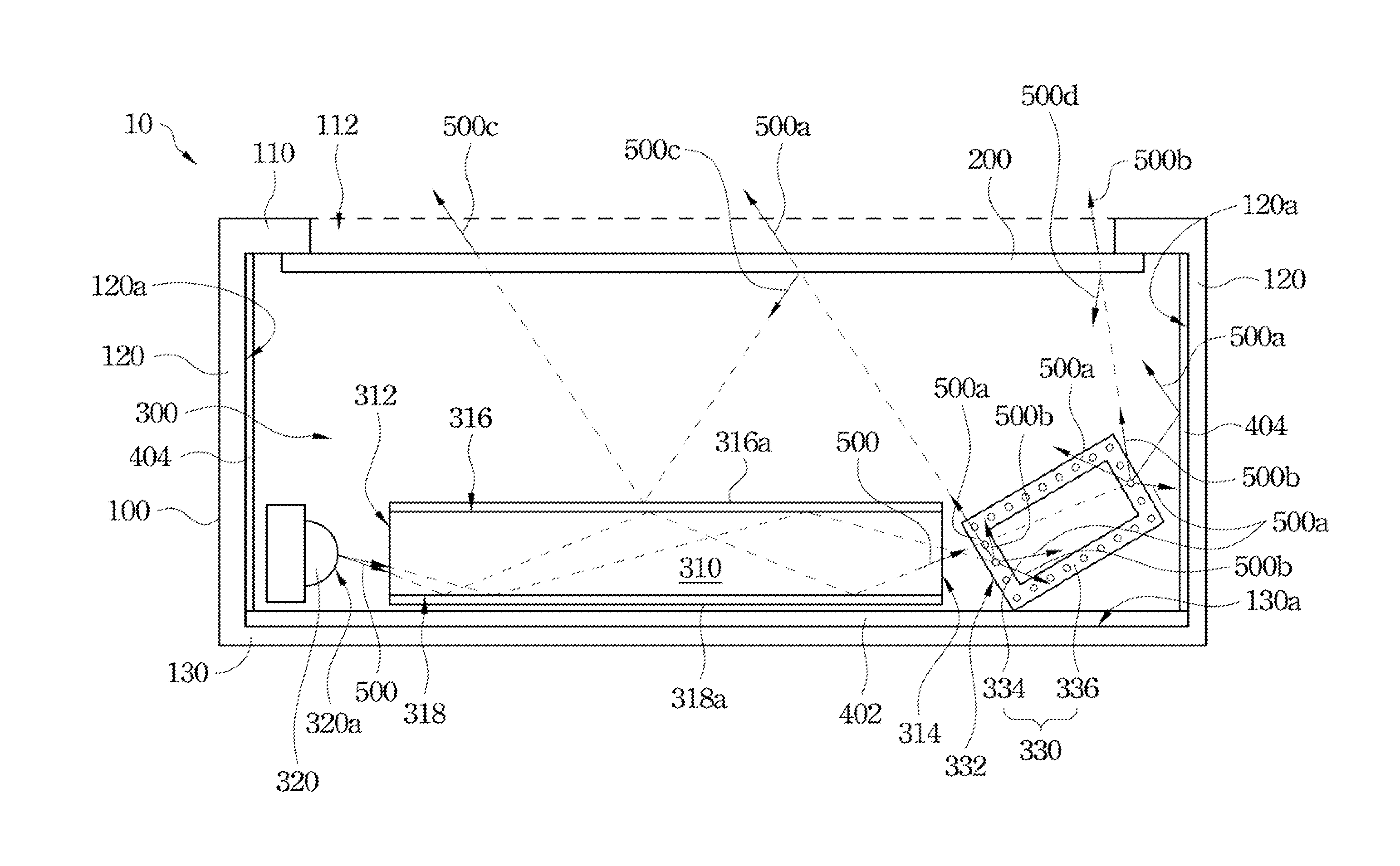
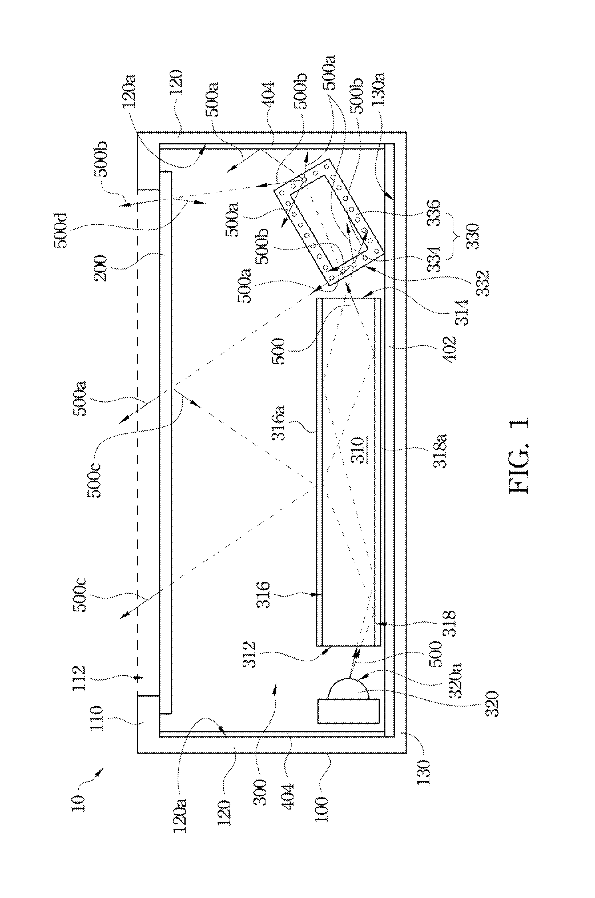
[0042]Referring to FIG. 1, FIG. 1 is a cross-sectional view of an illumination module according to one embodiment of the present invention. An illumination module 10 includes a case 100, a light-transmitting window 200 and a light source module 300. The case 100 includes a top plate 110, four side plates 120 and a bottom plate 130. The top plate 110 is opposite to the bottom plate 130, and the side plates 120 are all connected between the top plate 110 and the bottom plate 130, in ...


PUM


Abstract

An illumination module is provided, and includes a case, a light-transmitting window and a light source module. The case includes a top plate having an opening. The light-transmitting window covers the opening of the top plate. The light source module includes a light guide element, a first reflective sheet, a second reflective sheet, at least one light source and a fluorescence member. The light guide element includes a light incident surface, a light-exiting surface, a first reflective surface and a second reflective surface. The first reflective sheet and the second reflective sheet are disposed on the first reflective surface and the second reflective surface respectively. A light-emitting surface of the light source faces the light incident surface of the light guide element. At least one section of the fluorescence member faces the light-exiting surface of the light guide element.

Description

RELATED APPLICATIONS[0001]This application claims priority to Taiwan Patent Application Serial Number 101113276, filed on Apr. 13, 2012, which is herein incorporated by reference.BACKGROUND[0002]1. Field of Invention[0003]This application relates to an illumination module, and more particularly to an illumination module with a fluorescence member.[0004]2. Description of Related Art[0005]A conventional illumination module often utilizes a tungsten lamp or a fluorescent lamp as a light source. However, the tungsten lamp or the fluorescent lamp has the disadvantages of large power consumption, less illumination efficacy and more heat generating, and thus the conventional light source does not meet the development tendency of modern lighting technologies and environmental requirements.[0006]A LED (Light Emitting Diode) is a common point light source, which has the advantages of high efficacy and more saving power, etc. Thus, the LED is desired to replace the conventional light source to...

Claims


Application Information

Patent Timeline
IPC IPC(8): F21V13/08
CPCF21K9/61F21K9/62F21K9/64G02B6/005
Inventor WU, YI-TSUOCHU, YEN-CHUAN
Owner RADIANT OPTO ELECTRONICS
Why Eureka
Try Eureka