Temperature sensor and temperature measurement method thereof

a temperature sensor and temperature sensor technology, applied in the direction of thermometers with a/d converters, instruments, heat measurement, etc., can solve the problems of undesired linearity of the temperature sensor, and achieve the effects of improving linearity, reducing the amount of power consumed by the temperature sensor, and increasing the accuracy of digital outpu

Inactive Publication Date: 2013-10-17
KOREA ADVANCED INST OF SCI & TECH
View PDF4 Cites 28 Cited by
  • Summary
  • Abstract
  • Description
  • Claims
  • Application Information

AI Technical Summary

Benefits of technology

[0023]According to an exemplary embodiment of the present invention, it is possible to reduce the amount of power consumed by a temperature sensor and increase accuracy of digital output by improving linearity.

Problems solved by technology

The temperature sensors developed up to now have been widely used, because they can achieve high performance by means of many compensation plans, but the entire performance depends on an ADC and a high-performance ADC is not suitable for low-power design.
Further, the temperature sensor may show undesired linearity.

Method used


Image

  • Temperature sensor and temperature measurement method thereof
  • Temperature sensor and temperature measurement method thereof
  • Temperature sensor and temperature measurement method thereof

Examples


Embodiment Construction

[0033]In the following detailed description, only certain exemplary embodiments of the present invention have been shown and described, simply by way of illustration. As those skilled in the art would realize, the described embodiments may be modified in various different ways, all without departing from the spirit or scope of the present invention. Accordingly, the drawings and description are to be regarded as illustrative in nature and not restrictive. Like reference numerals designate like elements throughout the specification.

[0034]In addition, throughout the specification, unless explicitly described to the contrary, the word “comprise” and variations such as “comprises” or “comprising”, will be understood to imply the inclusion of stated elements but not the exclusion of any other elements.

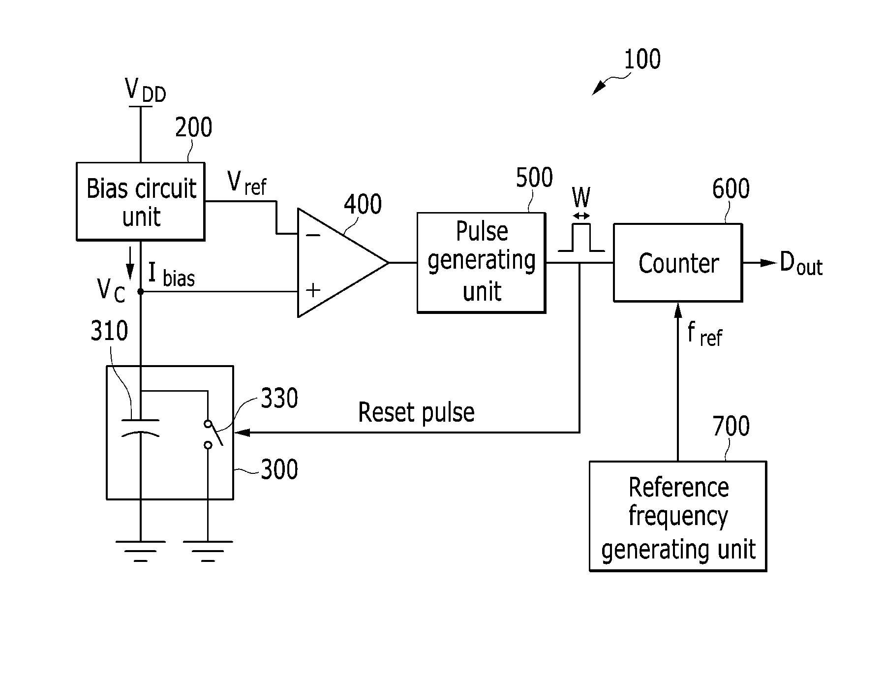
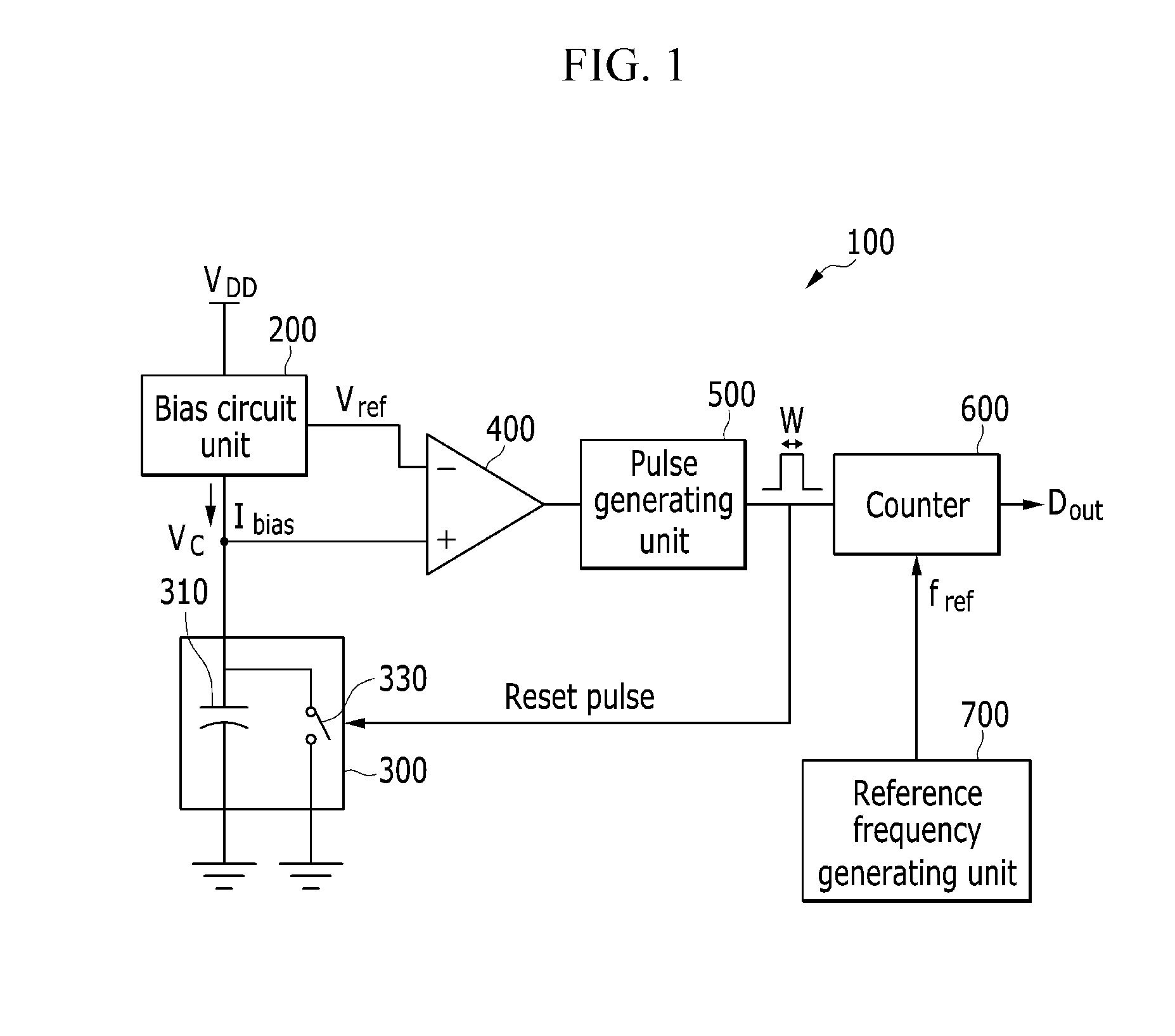
[0035]A temperature sensor according to an exemplary embodiment of the present invention is described with reference to the drawings.

[0036]FIG. 1 is a block diagram of a temperature sensor ...


PUM

PropertyMeasurementUnit
temperatureaaaaaaaaaa
bias currentaaaaaaaaaa
voltageaaaaaaaaaa

Abstract

A temperature sensor that senses a temperature on the basis of a relaxation oscillator, includes: a bias circuit unit that outputs a bias current increasing with an increase in temperature; a capacitor voltage unit that charges a capacitor with the bias current and discharges the current when receiving a control signal; a pulse generating unit that outputs a pulse when the voltage of the capacitor is higher than a reference voltage, changes the pulse width of the pulse, and transmits the pulse corresponding to the control signal to the capacitor voltage unit; and a counter unit that counts and outputs, as a digital value, the number of pulses outputted from the pulse generating unit, on the basis of a reference frequency.

Description

CROSS-REFERENCE TO RELATED APPLICATION[0001]This application claims priority to and the benefit of Korean Patent Application No. 10-2012-0038608 filed in the Korean Intellectual Property Office on Apr. 13, 2012, the entire contents of which are incorporated herein by reference.BACKGROUND[0002](a) Field[0003]The present invention relates to a temperature sensor and a temperature measurement method thereof.[0004](b) Description of the Related Art[0005]Temperature sensors that generate digital output can be implemented in various ways. Recently, temperature sensors are used by an application for RFID and a study of a temperature sensor that consumes less power has been conducted. The temperature sensors developed up to now output a change in voltage or current, which increases in proportion to a temperature, to an analog-digital converter.[0006]The temperature sensors developed up to now have been widely used, because they can achieve high performance by means of many compensation plan...

Claims


Application Information

Patent Timeline
Patent Type & Authority Applications(United States)
IPC IPC(8): G01K7/34
CPCG01K7/34G01K7/01G01K2219/00
Inventor LEE, SANG GUGJUNG, OHYONGKIM, SEUNGJINHAN, SEOK KYUN
Owner KOREA ADVANCED INST OF SCI & TECH
Why Eureka
Try Eureka