
Method and apparatus for estimating location of pedestrian using step length estimation model parameters

a technology of step length and estimation model, applied in the field of pedestrian dead reckoning, can solve the problems of increasing the error in heading information, continuously accumulating location errors, and large errors

Active Publication Date: 2013-10-17
ELECTRONICS & TELECOMM RES INST
View PDF6 Cites 16 Cited by
  • Summary
  • Abstract
  • Description
  • Claims
  • Application Information

AI Technical Summary

Benefits of technology

The present invention aims to solve problems in prior art by providing a method to accurately estimate step length and positioning information without the need for separate calibration procedures. Additionally, user equipment can provide sensor measurement information per step to a server, allowing for optimal positioning and navigation information.

Problems solved by technology

In particular, in the case of the procedure for estimating a step length, when a location error occurs, the location error is continuously accumulated as walking continues, and so the accuracy of the step length is very important in precise positioning.
That is, the magnetometer has an advantage of providing absolute orientation, but reacts sensitively to a surrounding environment influencing the gyroscope, and thus a large error may occur.
Meanwhile, since the gyroscope outputs angular velocity information, it reacts promptly to a sudden heading change of a pedestrian, but has a disadvantage of increasing an error in heading information as a step count increases, because relative orientation is estimated using integral calculus.
Generally, when off-line calibration is applied to a step length estimation procedure, there is inconvenience in that the user of normal UE must perform a separate calibration procedure so as to use location information.
For such calibration, the location of a designated interval or reference locations must be accurately known, and then the convenience of service usage is deteriorated.
Further, when on-line calibration is applied, there is a disadvantage in that it is difficult to receive GPS signals, and in that in an indoor environment in which a wireless communication infrastructure, such as a WiFi infrastructure, is not installed, such calibration cannot be performed.

Method used


Image

  • Method and apparatus for estimating location of pedestrian using step length estimation model parameters
  • Method and apparatus for estimating location of pedestrian using step length estimation model parameters
  • Method and apparatus for estimating location of pedestrian using step length estimation model parameters

Examples


Embodiment Construction

[0037]The present invention will be described in detail below with reference to the accompanying drawings. In the following description, redundant descriptions and detailed descriptions of known functions and elements that may unnecessarily make the gist of the present invention obscure will be omitted. Embodiments of the present invention are provided to fully describe the present invention to those having ordinary knowledge in the art to which the present invention pertains. Accordingly, in the drawings, the shapes and sizes of elements may be exaggerated for the sake of clearer description.

[0038]Hereinafter, preferred embodiments of the present invention will be described in detail with reference to the attached drawings.

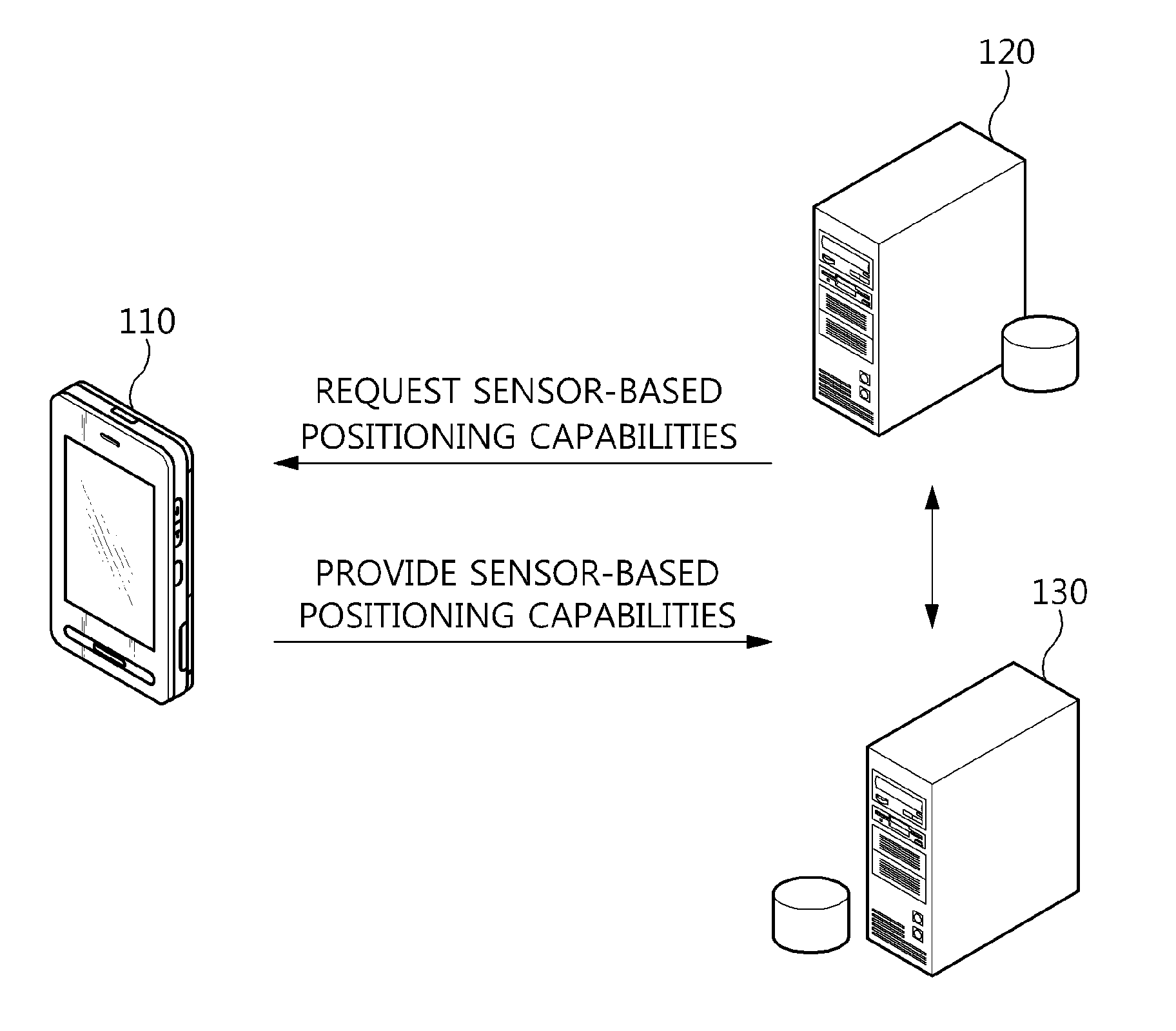
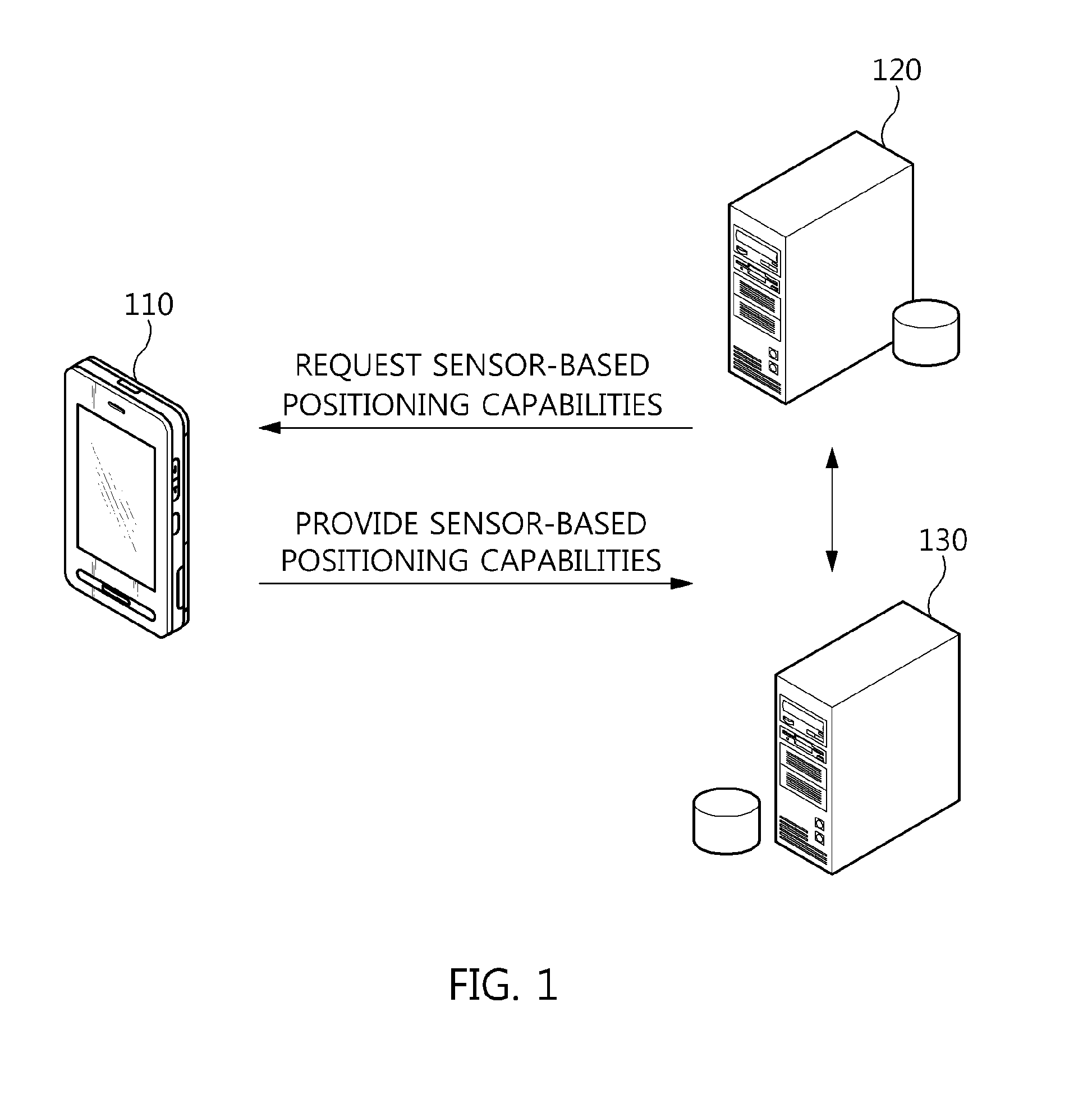
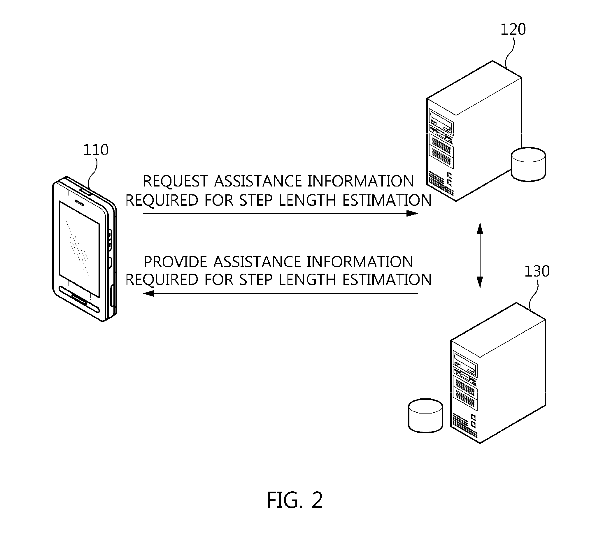
[0039]FIGS. 1 to 3 are diagrams showing a system to which a method of estimating the location of a pedestrian is applied according to an embodiment of the present invention.

[0040]Referring to FIG. 1, the system to which the pedestrian location estimation method i...


PUM


Abstract

Disclosed herein is a method and apparatus for estimating the location of a pedestrian using step length estimation model parameters. In the method of estimating a location of a pedestrian according to the present invention, mobile User Equipment (UE) having sensors generates positioning measurement information. The mobile UE requests positioning assistance information from a positioning server. The positioning server generates the positioning assistance information. The positioning server provides the positioning assistance information to the mobile UE. The mobile UE performs location estimation of the pedestrian using the positioning measurement information and the positioning assistance information.

Description

CROSS REFERENCE TO RELATED APPLICATIONS[0001]This application claims the benefit of Korean Patent Application Nos. 10-2012-0038390 filed on Apr. 13, 2012 and 10-2012-0099256 filed on Sep. 7, 2012, which are hereby incorporated by reference in their entireties into this application.BACKGROUND OF THE INVENTION[0002]1. Technical Field[0003]The present invention relates generally to Pedestrian Dead Reckoning (PDR) and, more particularly, to a method and apparatus that receive step length estimation model parameters from a server and utilize the parameters when a terminal (user equipment: UE) including sensors, such as an accelerometer, a gyroscope, and a magnetometer, calculates its location through PDR for estimating a step count, a step length, and direction (heading) information using the sensors, thus promptly and accurately providing location information immediately upon receiving a location request, without requiring an additional calibration operation in the user equipment. Furth...

Claims


Application Information

Patent Timeline
Patent Type & Authority Applications(United States)
IPC IPC(8): H04W64/00
CPCH04W64/00G01C21/165G01C22/006
Inventor CHO, YOUNG-SUJI, MYUNG-IN
Owner ELECTRONICS & TELECOMM RES INST
Learn More