Centrifugal separator and a liquid phase discharge port member

a centrifugal separator and liquid phase technology, applied in centrifuges, rotary centrifuges, etc., can solve problems such as liquid discharge, and achieve the effects of facilitating the process of exchanging weir plates, low feed rate, and low liquid level in the bowl

Active Publication Date: 2013-10-17
ALFA LAVAL CORP AB
View PDF17 Cites 9 Cited by
  • Summary
  • Abstract
  • Description
  • Claims
  • Application Information

AI Technical Summary

Benefits of technology

[0009]Placing the weir at the discharge opening ensures that the level of liquid in the bowl is maintained substantially constant at all feed rates since the discharged liquid simply flows over the top of the weir plate, the weir plate thus determining the level of liquid in the casing and thereby the bowl. Moving the discharge opening and the weir away from the outlet opening ensures that no liquid will cling to the outside of the base plate. Thereby a loss of energy that can be in the range of 10% to 15% may be avoided. Further energy of the rotating liquid can be regained at the discharge opening, resulting in a power gain that can be in the range of 10% to 15%, when the liquid is discharged in the opposite direction relative to the direction of rotation.
[0012]According to an embodiment of the invention the weir comprises a hole. The hole prevents liquid from flowing out of the bowl through the solid discharge opening during the start-up period by providing a liquid outlet effective at start-up conditions with a low feed rate to provide a low level of liquid in the bowl.
[0013]According to a preferred embodiment of the invention the weir is provided as an exchangeable weir plate, whereby the level of the overflow edge may be changed to correspond to the desired level of liquid in the bowl. According to a further preferred embodiment of the invention grooves are provided at said discharge opening, which are adapted to receive said weir plate. Hereby the process of exchanging the weir plate is facilitated considerably, and correct installation of the weir plate is ensured at all times.
[0014]According to another preferred embodiment of the invention the casing comprises a curved wall extending from the base plate to a remote side of said casing side, a side of the discharge opening being flush with the curved wall. Such a configuration provides an internal surface of the casing that causes little turbulence in the discharged liquid, thereby further reducing the power consumption.
[0017]With a liquid phase discharge port member according to the invention it is possible to adapt an existing centrifugal separator to achieve the abovementioned advantages simply by attaching a liquid phase discharge port member according to the invention over the liquid phase outlet ports of the separator.

Problems solved by technology

However in case a plurality of outlets with casings projecting from the base plate of the bowl is provided an angle of 0° may result in liquid discharged from one outlet colliding with an adjacent casing projecting from the base plate of the bowl.

Method used


Image

  • Centrifugal separator and a liquid phase discharge port member
  • Centrifugal separator and a liquid phase discharge port member
  • Centrifugal separator and a liquid phase discharge port member

Examples


Embodiment Construction

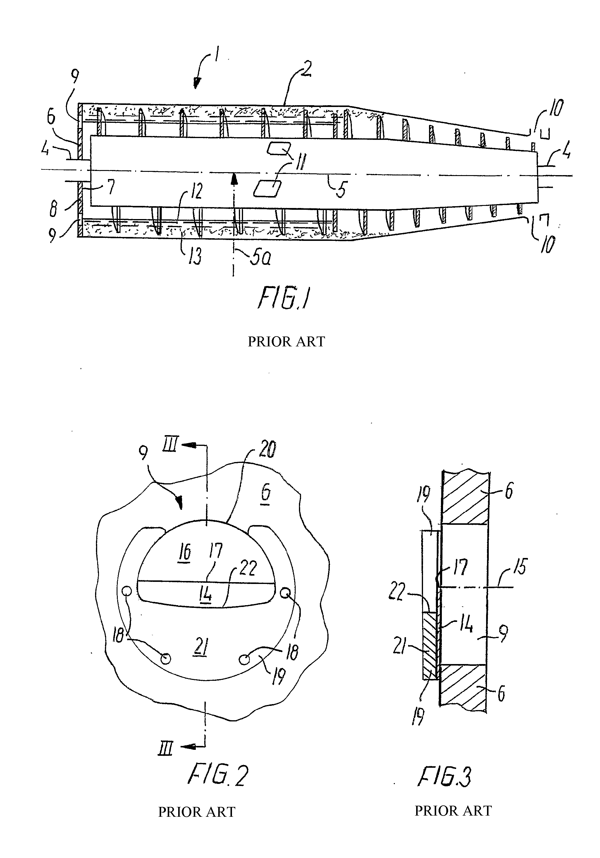
[0028]A prior art centrifugal separator 1 shown in FIG. 1 comprises a bowl 2 and a screw conveyor 3 which are mounted on a shaft 4 such that in use they can be brought to rotate around an axis 5, the axis of rotation 5 extending in a longitudinal direction of the bowl 2. Further, the centrifugal separator 1 has a radial direction 5a extending substantially perpendicular to the longitudinal direction.

[0029]For the sake of simplicity directions “up” and “down” are used herein as referring to a radial direction towards the axis of rotation 5 and away from the axis of rotation, respectively.

[0030]The bowl 2 comprises a base plate 6 provided at one longitudinal end of the bowl 2, which base plate 6 has an internal side 7 and an external side 8. The base plate 6 is provided with a number of liquid phase outlet openings 9. Furthermore the bowl 2 is at an end opposite to the base plate 6 provided with solid phase discharge openings 10.

[0031]Further the screw conveyor 3 comprises inlet openi...


PUM


Abstract

A centrifugal separator comprises a bowl rotating in use around an axis of rotation. The axis of rotation extends in a longitudinal direction, and a radial direction extends perpendicular to the longitudinal direction. A base plate provided at one longitudinal end of the bowl, said base plate having an internal and external side, an outlet opening being provided in the base plate. A casing is projecting at the outlet opening on the external side of said base plate, said casing comprising a casing side, a normal to said casing side extending at an acute angle relative to a circumferential direction of the bowl at said casing and a discharge opening is provided in said casing side. The discharge opening is radially outwardly limited by a weir with an overflow edge and said discharge opening extending radially inwardly to a position above a highest intended level of liquid in the bowl.

Description

CROSS-REFERENCE TO RELATED APPLICATION[0001]This application is a Continuation Application of U.S. patent application Ser. No. 12 / 599,106, filed on Dec. 30, 2009, the contents of which are incorporated herein by reference in its entirety and the benefits are fully claimed herein. This application is also entitled to the benefit of and incorporates by reference essential subject matter disclosed in International Application No. PCT / DK2008 / 050102 filed on May 8, 2008 and Danish Patent Application No. PA 2007 00697 filed on May 9, 2007.FIELD OF THE INVENTION[0002]The present invention relates to a centrifugal separator comprising a bowl rotatable about an axis of rotation, said axis of rotation extending in a longitudinal direction of said bowl, a base plate provided at one longitudinal end of said bowl, said base plate having an internal side and an external side, an outlet opening provided in said base plate, a casing projecting at the outlet opening on the external side of said base...

Claims


Application Information

Patent Timeline
Patent Type & Authority Applications(United States)
IPC IPC(8): B04B11/00
CPCB04B11/00B04B1/20B04B2001/2075B04B2001/2083B04B1/14B04B11/02
Inventor MADSEN, BENTDIRCKS, KLAUS
Owner ALFA LAVAL CORP AB
Why Eureka
Try Eureka