Supply independent current reference generator in CMOS technology

a current reference and generator technology, applied in the direction of electric variable regulation, process and machine control, instruments, etc., can solve the problems of inability to manufacture precision resistors, inability to meet the requirements of the supply voltage, and undesirable dependence on the supply voltage, so as to achieve the effect of constant current level

Inactive Publication Date: 2012-08-30
SILICON LAB INC
View PDF3 Cites 6 Cited by
  • Summary
  • Abstract
  • Description
  • Claims
  • Application Information

AI Technical Summary

Benefits of technology

[0005]A current reference generator including a current network, a bias network, and a loop amplifier. The current network includes first second and transistors of a first conductivity type and third, fourth and fifth transistors of a second conductivity type. The first and second transistors each have a first current terminal coupled to a first supply line and a control terminal coupled to a first node. The first transistor has a second current terminal coupled to a second node and the second transistor has a second current terminal coupled to a third node. The third transistor has a first current terminal coupled to the second node, a control terminal coupled to a fourth node, and a second current terminal coupled to a fifth node. The fourth transistor has a first current terminal coupled to the third node, a control terminal coupled to the fourth node, and a second current terminal coupled to a second supply line. The fifth transistor has a first current terminal coupled to the fifth node, a second current terminal coupled to the second supply line, and has a control terminal. The bias network is coupled to at least one of the supply lines and has a control output coupled to the control terminal of the fifth transistor. The loop amplifier is coupled to the current network and is operative to maintain relatively constant current level through the current terminals of the fifth transistor.
[0006]In a first configuration, the third transistor is diode-coupled in which the second and fourth nodes are coupled together, and the loop amplifier has an input coupled to the third node and an output driving the first node. In a more specific first configuration, the loop amplifier is implemented using a sixth transistor of the first conductivity type and a seventh transistor of the second conductivity type. The sixth transistor has a first current terminal coupled to the first supply line and is diode-coupled having a second current terminal and a control terminal coupled together at the first node. The seventh transistor in this configuration has a first current terminal coupled to the first node, a second current terminal coupled to the second supply line, and a control terminal coupled to the third node. A capacitor may be provided and coupled between the control terminal of the seventh transistor and the second supply line.
[0007]In a second configuration, the second transistor is diode-coupled in which the first and third nodes are coupled together, and the loop amplifier has an input coupled to the second node and an output driving the fourth node. In a more specific second configuration, the loop amplifier is implemented using a sixth transistor of the first conductivity type and a seventh transistor of the second conductivity type. The sixth transistor has a first current terminal coupled to the first supply line, a control terminal coupled to the second node, and a second current terminal coupled to the fourth node. The seventh transistor in this configuration is diode-coupled having a first current terminal and a control terminal coupled together at the fourth node, and has a second current terminal coupled to the second supply line. A capacitor may be provided and coupled between the control terminal of the sixth transistor and the second supply line.
[0008]In any of these configurations, a startup network may be provided to initiate desired current flow through the current branches of the current network. Also, one or more reference or output devices may be provided to tap a reference current for use. Dual configurations are also contemplated by swapping polarities of the supply lines and the transistor types.

Problems solved by technology

Resistors can also be problematic since they generally consume a significant amount of space, and precision resistors are relatively difficult to fabricate.
The primary configuration described therein, however, also exhibited an undesirable degree of dependence upon the supply voltage.
Although MOS devices do not completely shut down when their gate-to-source voltage (VGS) is below VT for sub-threshold operation, the current becomes very low during sub-threshold operation so that VT is a practical limitation for reliable operation.
Nonetheless, the requirement that the current generator operate with a supply voltage of about 2VT prevents the full benefits of the lower voltage technologies.
The higher voltage level is not advantageous for certain applications, such as battery-operated devices with limited supply voltage range.

Method used


Image

  • Supply independent current reference generator in CMOS technology
  • Supply independent current reference generator in CMOS technology
  • Supply independent current reference generator in CMOS technology

Examples


Embodiment Construction

[0016]The following description is presented to enable one of ordinary skill in the art to make and use the present invention as provided within the context of a particular application and its requirements. Various modifications to the preferred embodiment will, however, be apparent to one skilled in the art, and the general principles defined herein may be applied to other embodiments. Therefore, the present invention is not intended to be limited to the particular embodiments shown and described herein, but is to be accorded the widest scope consistent with the principles and novel features herein disclosed.

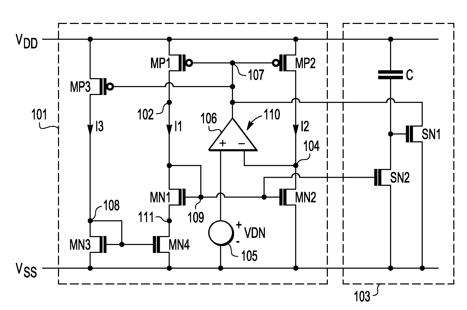
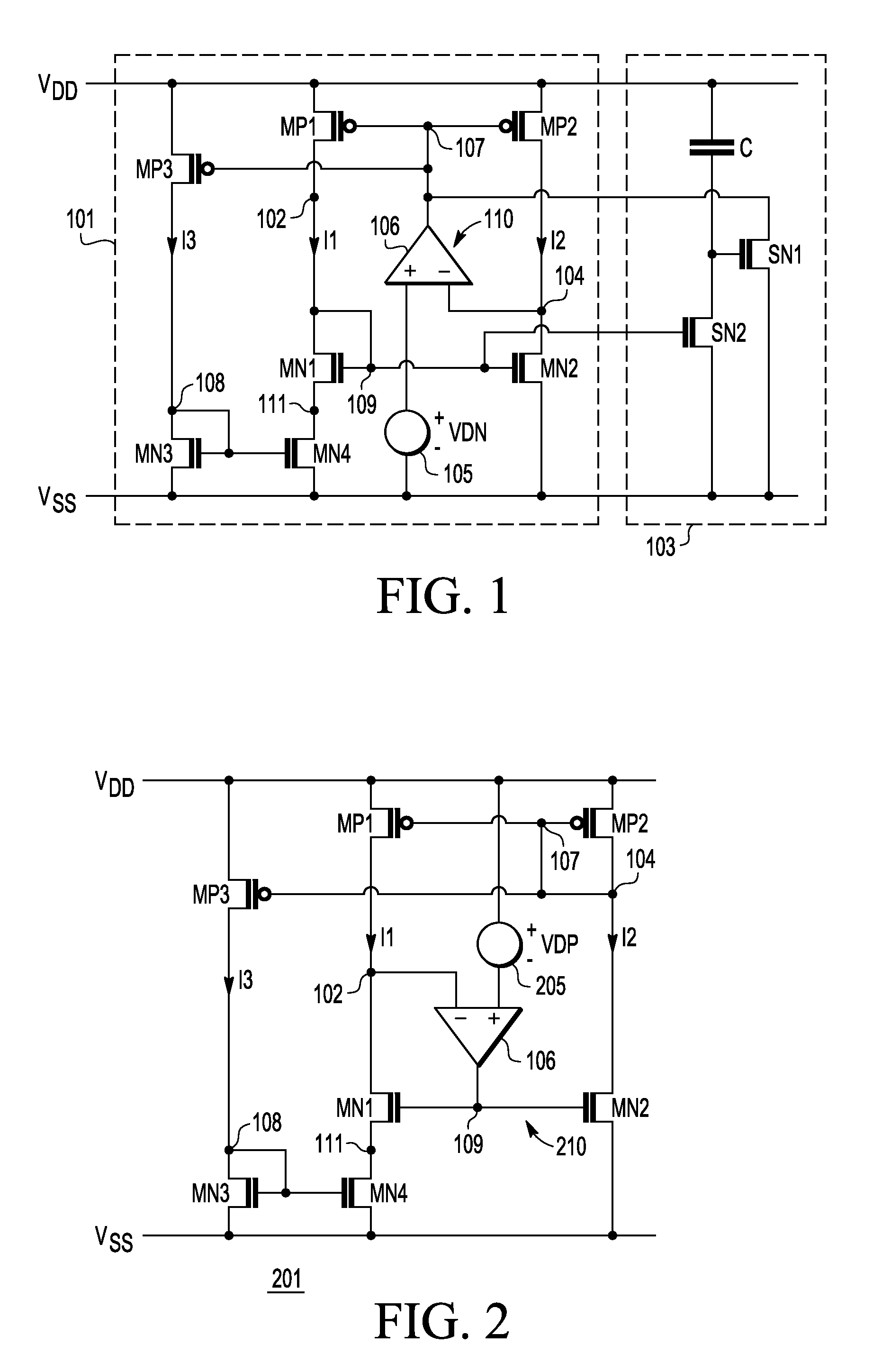
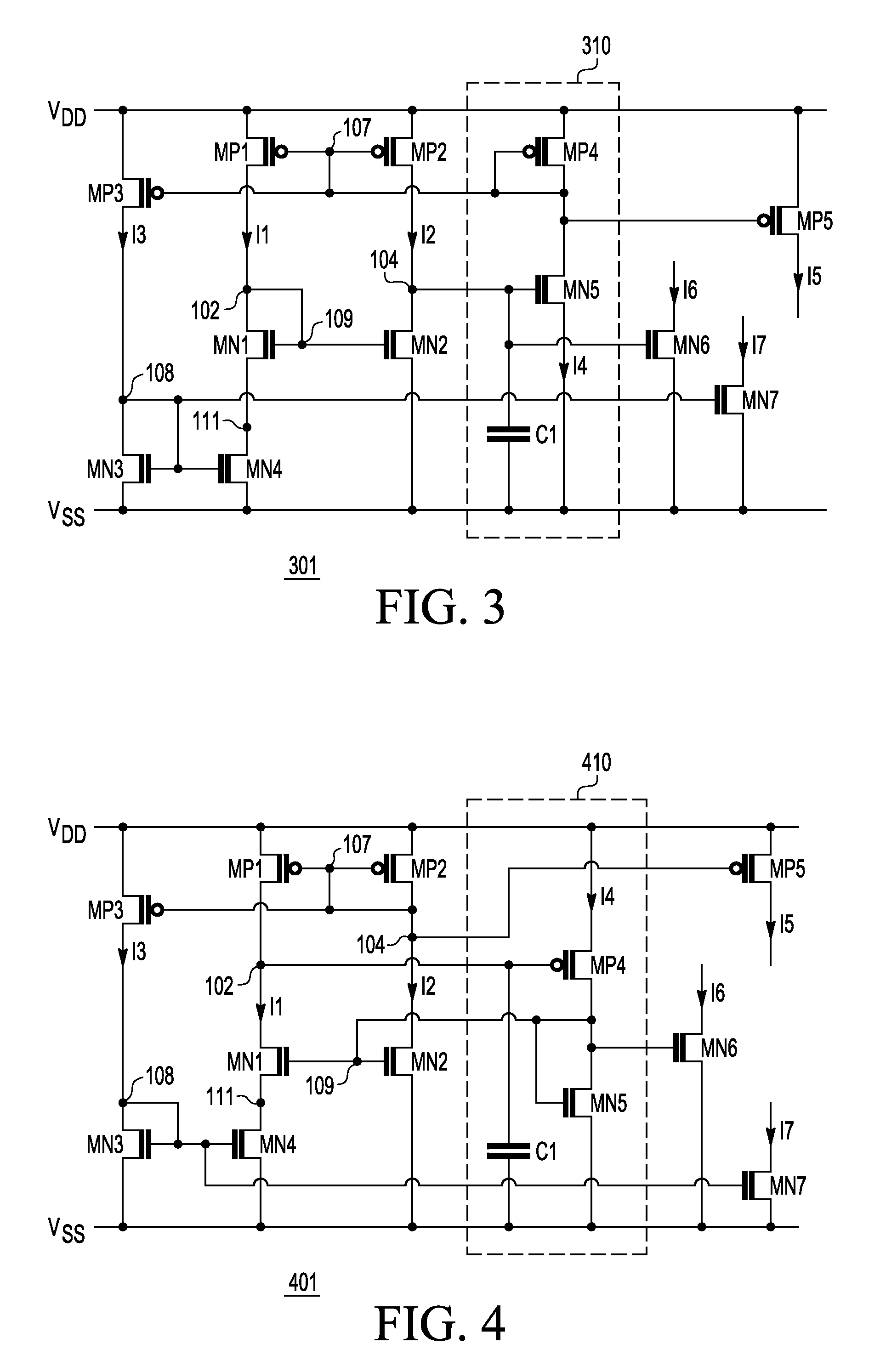
[0017]FIG. 1 is a schematic diagram of a current reference generator 101 implemented according to one embodiment coupled to a startup network 103. The current reference generators described herein are implemented using transistors of complementary conductivity types, such as P-type or P-channel metal-oxide semiconductor (MOS) transistors (or PMOS transistors) and N-type or N-ch...


PUM


Abstract

A current reference generator including a current network, a bias network, and a loop amplifier. The current network includes first and second transistors of a first conductivity type and third, fourth and fifth transistors of a second conductivity type. The first, third and fifth transistors are series-coupled between voltage supply lines forming a first current path, and the second and fourth transistors are series-coupled between the supply lines forming a second current path. The control terminals of the first and second transistors are coupled together and the control terminals of the third and fourth transistors are coupled together. The bias network biases the fifth transistor. The loop amplifier is coupled to the current network and is operative to maintain constant current level through the first and second current paths independent of voltage variations of the supply lines and at very low supply voltage.

Description

FIELD OF THE INVENTION[0001]The present invention relates in general to current reference generators in CMOS technology, and particularly to CMOS current reference generators that are capable of operating with very low supply voltage.BACKGROUND OF THE INVENTION[0002]A current reference generator is a useful component for providing a known current level within an electronic circuit. Classic current reference generators were typically implemented using bipolar transistors and resistors and the like. Many modern electronic devices, however, are implemented using complementary metal-oxide semiconductor (CMOS) technology for reduced size and power consumption. CMOS technology, for example, is particularly advantageous for smaller and / or lower power electronic devices including those which are powered by a battery. Although bipolar devices may be integrated along with CMOS devices on a common chip (e.g., BiCMOS or BiMOS), it is preferred to implement as many devices components as possible...

Claims


Application Information

Patent Timeline
Patent Type & Authority Applications(United States)
IPC IPC(8): G05F3/28
CPCG05F3/262
Inventor FONDERIE, M. JEROEN
Owner SILICON LAB INC
Why Eureka
Try Eureka