Ultrasound diagnostic imaging apparatus

a diagnostic imaging and ultrasonic technology, applied in the field of ultrasonic diagnostic imaging apparatus, can solve the problems of inability to determine the depth inability to figure out the exact position of the puncture needle, and the frame rate decrease in exchange for determining the puncture needle. , to achieve the effect of reducing the frame ra

Active Publication Date: 2013-10-17
KONICA MINOLTA MEDICAL & GRAPHICS INC
View PDF5 Cites 14 Cited by
  • Summary
  • Abstract
  • Description
  • Claims
  • Application Information

AI Technical Summary

Benefits of technology

[0007]The present invention was made in consideration of the above problems and an object of the present invention is to provide an ultrasonic diagnostic imaging apparatus which can figure out the position of a puncture needle while the decrease in frame rate is reduced.

Problems solved by technology

However, since the technique disclosed in JP 2006-320378 requires transmitting and receiving ultrasound in multiple directions in order to determine the direction of the puncture needle, there is a problem that the frame rate decreases in exchange for determining the puncture needle.
Also, although the technique disclosed in JP 2006-320378 enables to figure out the angle of the puncture needle from the transmitting and receiving directions of the ultrasound and the puncture angle defined by the puncture needle insertion attachment, it cannot determine the depth of the puncture needle.
It is thus impossible to figure out the exact position of the puncture needle.

Method used


Image

  • Ultrasound diagnostic imaging apparatus
  • Ultrasound diagnostic imaging apparatus
  • Ultrasound diagnostic imaging apparatus

Examples


Embodiment Construction

[0055]Hereinafter, a medical image management system according to embodiments of the present invention will be described with reference to the drawings. However, the scope of the invention is not limited to the examples shown in the drawings. In the following descriptions, same references are used for same functions and configurations and their descriptions are omitted.

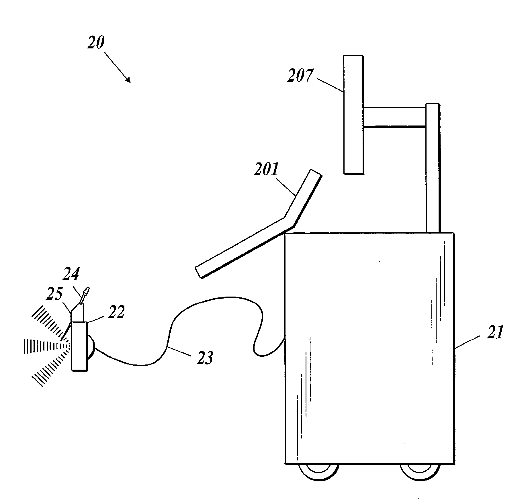
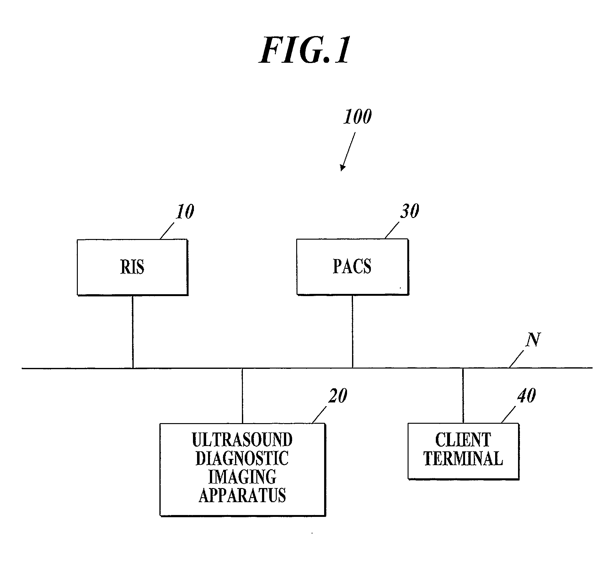
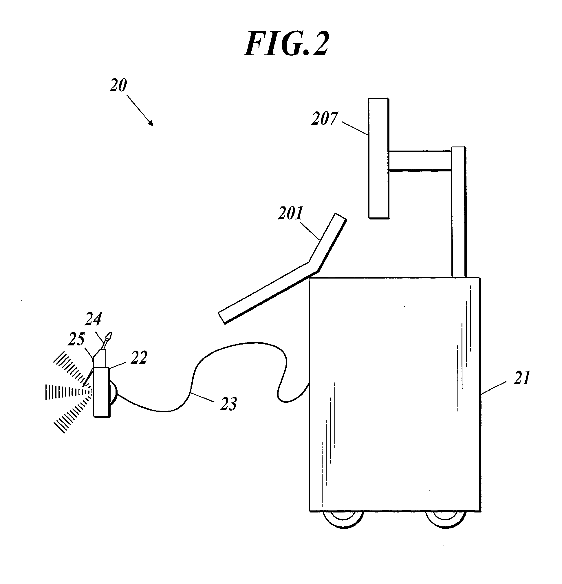
[0056]As shown in FIG. 1, a medical image management system 100 includes an RIS (radiological information system) 10, an ultrasound diagnostic imaging apparatus 20, a PACS (picture archiving and communication system) 30 and a client terminal 40.

[0057]These apparatuses are each connected to one another through a communication network N such as LAN (local area network) so that data communication is possible. The medical image management system 100 may be connected with a different type of modality from the ultrasound diagnostic imaging apparatus 20, for example, such as a CT (computed tomography apparatus), MRI (magneti...


PUM


Abstract

Disclosed is an ultrasound diagnostic imaging apparatus including an ultrasound probe which outputs a transmission ultrasound toward a subject and a received signal obtained by receiving a reflected ultrasound from the subject, a transmission unit, a receiving unit and a puncture needle position detection unit which obtains a puncture needle echo information indicating an angle and a position of the puncture needle from the plane-wave received signal, and an ultrasound image is displayed on the basis of the received signal, the transmission unit applies the driving signal to the ultrasound probe so that a plane-wave transmission ultrasound is output from the ultrasound probe, and the receiving unit receives a plane-wave received signal which is obtained in such a way that the plane-wave transmission ultrasound is transmitted from the ultrasound probe, reflected by a puncture needle to be the reflected ultrasound and received by the ultrasound probe.

Description

BACKGROUND OF THE INVENTION[0001]1. Field of the Invention[0002]The present invention relates to an ultrasound diagnostic imaging apparatus.[0003]2. Description of Related Art[0004]Biopsy has been long performed where a puncture needle is inserted to a living body to sample a tissue or body fluid which is to be diagnosed. In order not to insert a puncture needle into an incorrect position when sampling a specific tissue or the like of a living body, the puncture needle is attached to an ultrasound probe equipped with an attachment or a guide, as well as an operator such as a doctor checks the position of the puncture by watching an ultrasound image which is based on ultrasound image data on the living body obtained by the ultrasound probe when he or she inserts the puncture needle.[0005]Among ultrasound diagnostic image apparatuses in the earlier development, there is one which distinctly displays a puncture needle in an ultrasound image in such a way that ultrasound is transmitted ...

Claims


Application Information

Patent Timeline
Patent Type & Authority Applications(United States)
IPC IPC(8): A61B8/08
CPCA61B8/0841A61B8/4405A61B8/4444
Inventor TAKEDA, YOSHIHIROKAJI, DAISUKE
Owner KONICA MINOLTA MEDICAL & GRAPHICS INC
Why Eureka
Try Eureka