Liquid crystal display device with dynamically switching driving method to reduce power consumption

a technology of dynamic switching and display device, which is applied in the direction of electric digital data processing, instruments, computing, etc., can solve the problems of reducing driving ability and source driver having more time to charge liquid crystal capacitors, so as to reduce power consumption, reduce frame rate, and reduce power consumption

Active Publication Date: 2009-05-21
AU OPTRONICS CORP
View PDF18 Cites 25 Cited by
  • Summary
  • Abstract
  • Description
  • Claims
  • Application Information

AI Technical Summary

Benefits of technology

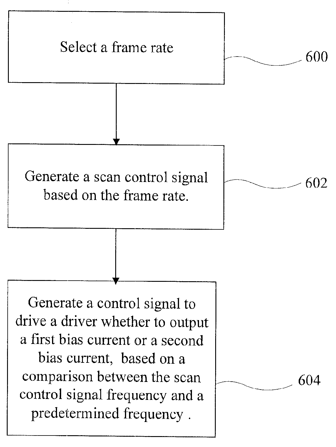
[0009]Therefore, an object of the present invention is to provide a liquid crystal display device having dynamically switching driving modes. In response to lower frame rate, the source driver according to the present inventive liquid crystal display device can adjust a bias current and / or turn on / off power-saving function such as charge recycling, to reduce power consumption. Because a time period of charging the liquid crystal capacitor delays, the source driver may have more time to charge the liquid crystal capacitors, even though the driving ability lowers. The source driver can selectively output different bias current and enable / disable power-saving function based on different frame rates, thereby reducing power consumption.

Problems solved by technology

Because a time period of charging the liquid crystal capacitor delays, the source driver may have more time to charge the liquid crystal capacitors, even though the driving ability lowers.

Method used


Image

  • Liquid crystal display device with dynamically switching driving method to reduce power consumption
  • Liquid crystal display device with dynamically switching driving method to reduce power consumption
  • Liquid crystal display device with dynamically switching driving method to reduce power consumption

Examples


first embodiment

[0023]Referring to FIG. 3 showing a schematic diagram of a liquid crystal display (LCD) device according to the present invention, the liquid crystal display device 100, which may be a personal computer and notebook computer, comprises a processing unit 101, an input interface 102, a timing controller 104, a source driver 106, a gate driver 108, and a liquid crystal display panel 110 having a plurality of pixel units 120, each pixel unit 120 of which comprises a transistor 122 and a liquid crystal capacitor 124. The processing unit 101 is used for controlling the operation of the LCD device 100. The source driver 106 and the gate driver 108 are disposed on a film (i.e. Chip on film, COF) or disposed on a glass substrate (i.e. Chip of glass, COG) and are electrically connected to other circuitry on a printed circuit board via a flexible printed circuit board. The timing controller 104 is coupled to the source driver 106 and the gate driver 108. Upon receiving clock signal from the ti...

second embodiment

[0032]Referring to FIG. 8 showing a schematic diagram of a liquid crystal display (LCD) device according to the present invention, the liquid crystal display device 200, which may be a personal computer and notebook computer, comprises a processing unit 201, an input interface 202, a timing controller 204, a source driver 106, a gate driver 108, and a liquid crystal display panel 110 having a plurality of pixel units 120, each pixel unit 120 of which comprises a transistor 122 and a liquid crystal capacitor 124. The processing unit 201 is used for controlling the operation of the LCD device 200. The source driver 106 and the gate driver 108 are disposed on a film (i.e. Chip on film, COF) or disposed on a glass substrate (i.e. Chip of glass, COG) and are electrically connected to other circuitry on a printed circuit board via a flexible printed circuit board. It is noted that, for simplicity, elements in FIG. 8 that have the same function as that illustrated in FIG. 3 are provided wi...


PUM


Abstract

A liquid crystal display device of reducing power consumption includes a liquid crystal panel having a plurality of liquid crystal capacitors for displaying an image, an input interface for generating a scan control signal, an oscillator for generating a predetermined frequency, a control unit electrically coupled to the oscillator for outputting a current control signal when a frequency of the scan control signal is lower than the predetermined frequency, and a driving circuit electrically coupled to the controller for generating a first bias current to charge the plurality of liquid crystal capacitors of the liquid crystal panel.

Description

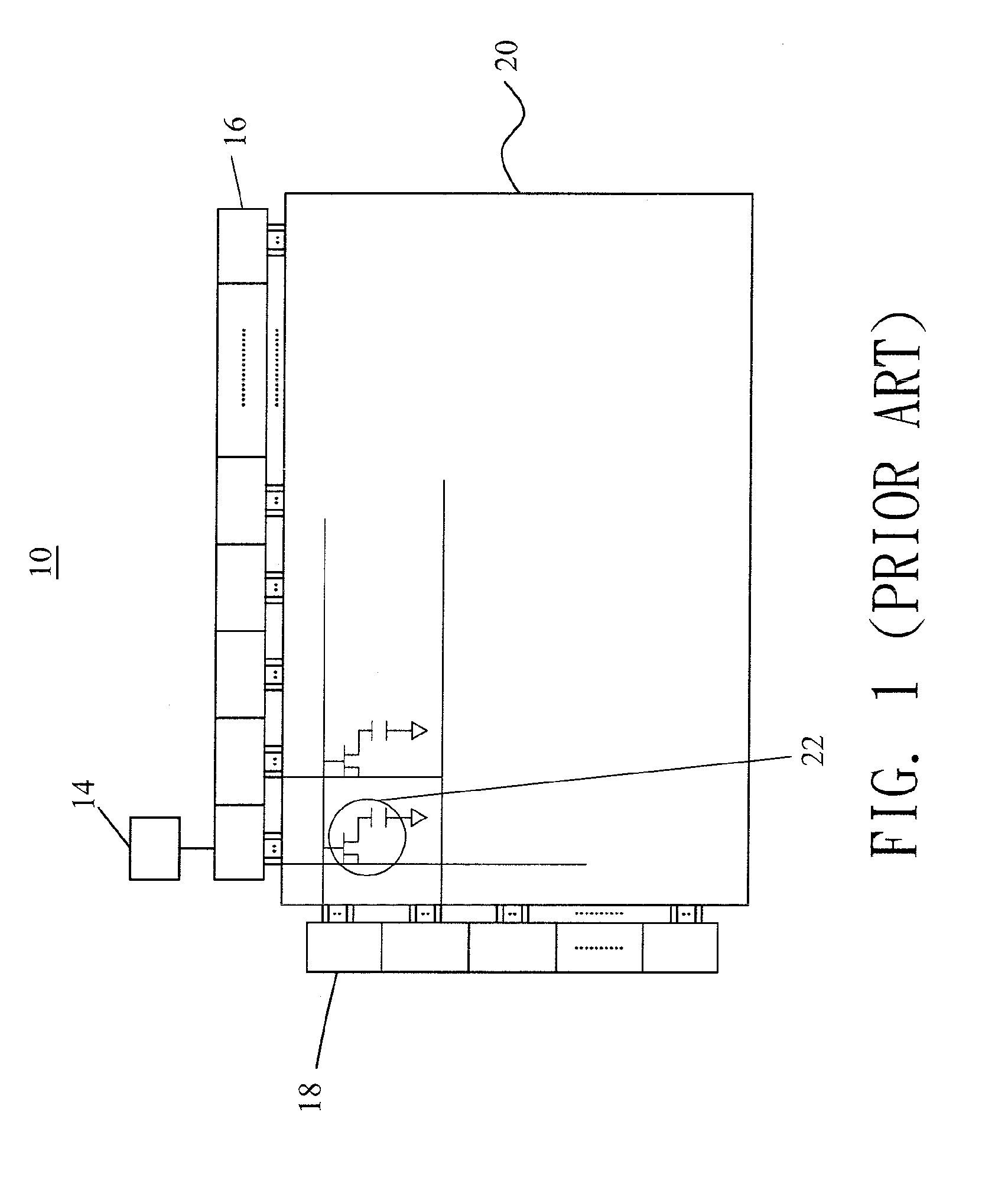
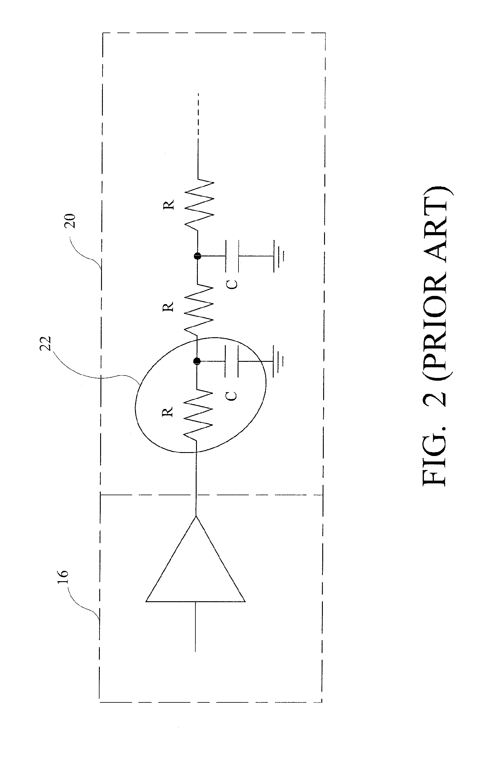
BACKGROUND OF THE INVENTION[0001]1. Field of the Invention[0002]The present invention relates to a liquid crystal display (LCD) device, and more specifically, to an LCD device having dynamically switching driving modes to reduce power consumption.[0003]2. Description of Prior Art[0004]With a rapid development of monitor types, novel and colorful monitors with high resolution, e.g., liquid crystal displays (LCDs), are indispensable components used in various electronic products such as monitors for notebook computers, personal digital assistants (PDAs), digital cameras, and projectors. The demand for the novelty and colorful monitors has increased tremendously.[0005]Referring to FIG. 1 showing a schematic diagram of a liquid crystal display device according to a prior art. Liquid crystal display device 10 contains a timing controller 14, a source driver 16, a gate driver 18, a gamma reference voltage generator 22, and a liquid crystal panel 20 having a plurality of pixel units 28. Up...

Claims


Application Information

Patent Timeline
Patent Type & Authority Applications(United States)
IPC IPC(8): G09G5/00G09G3/36
CPCG09G3/3611G09G3/3648G09G2310/0251G09G2340/0435G09G2330/021G09G2330/022G09G2330/023G09G2330/02
Inventor HSU, CHAO-CHING
Owner AU OPTRONICS CORP
Why Eureka
Try Eureka