Wiper lever assembly and wiper blade

Active Publication Date: 2013-10-24
DENSO CORP +2
View PDF3 Cites 1 Cited by
  • Summary
  • Abstract
  • Description
  • Claims
  • Application Information

AI Technical Summary

Benefits of technology

[0006]Accordingly, the present invention provides a wiper lever assembly and a wiper blade which are capable of preventi

Problems solved by technology

However, in this configuration is may be difficult to form a slanted surface on the pivot s

Method used


Image

  • Wiper lever assembly and wiper blade
  • Wiper lever assembly and wiper blade
  • Wiper lever assembly and wiper blade

Examples


Example

[0028]

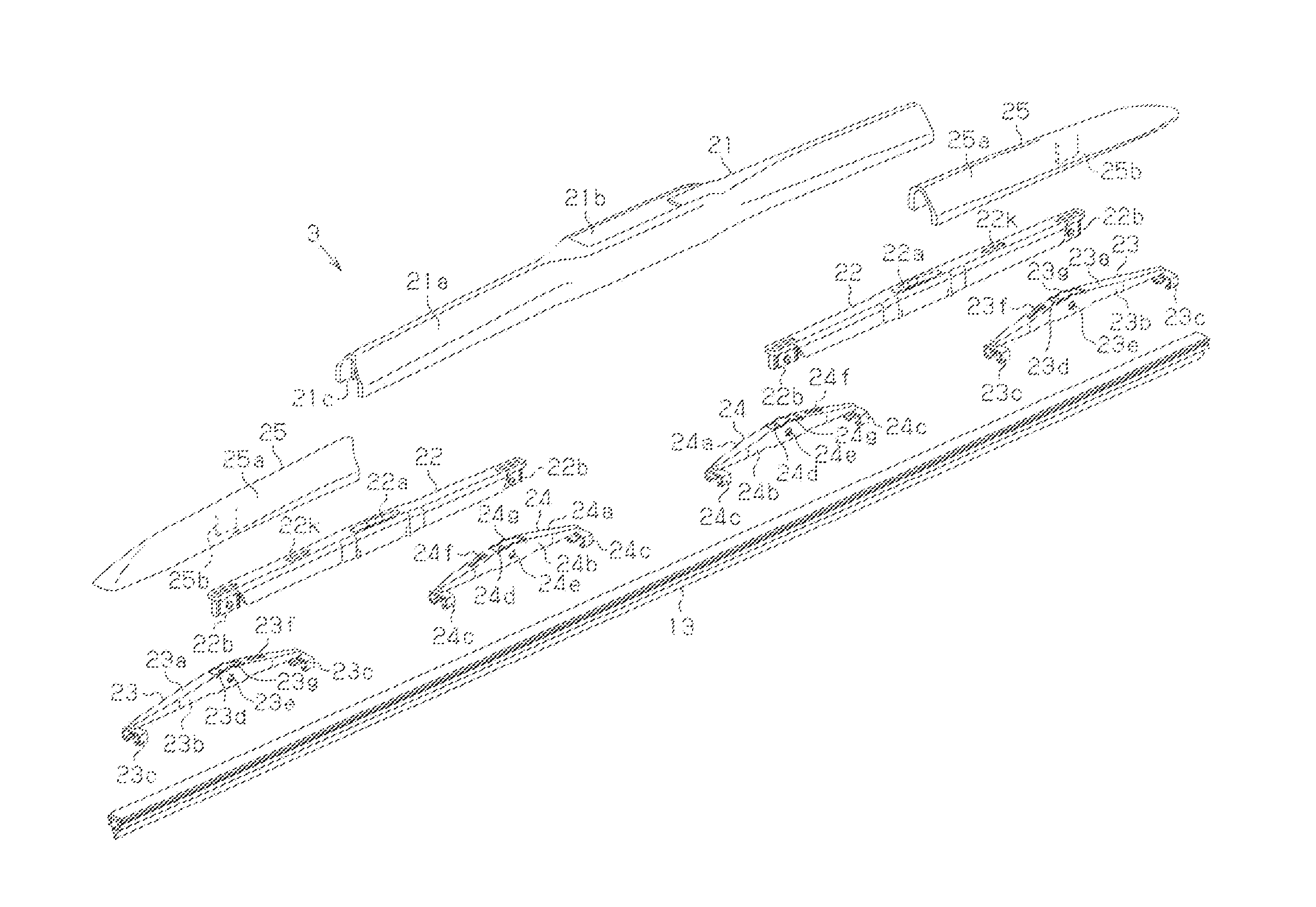
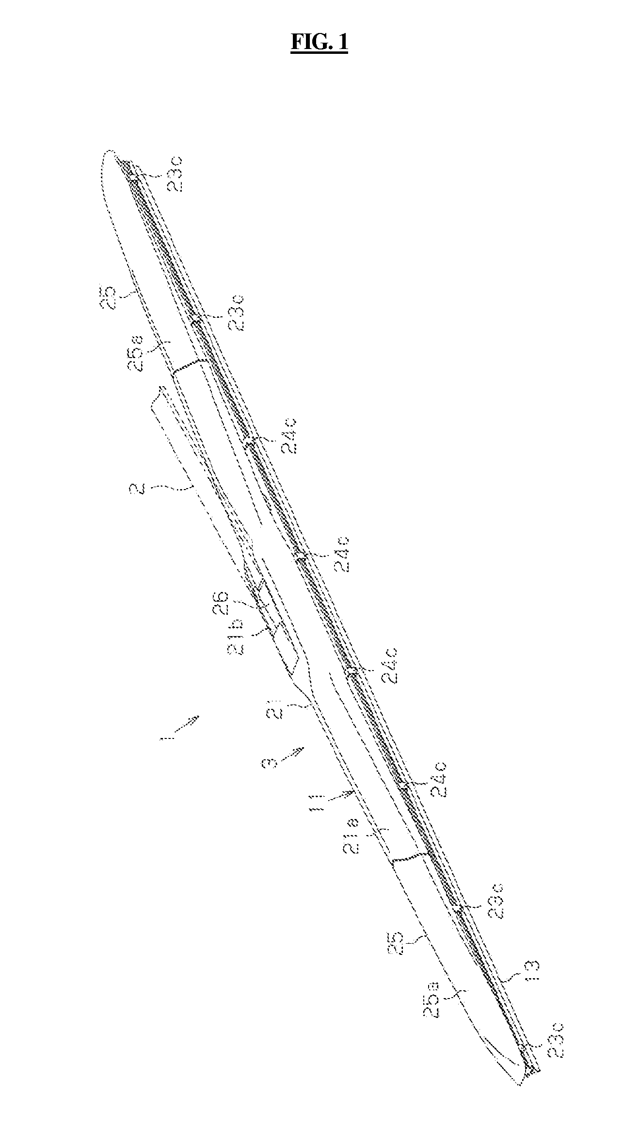
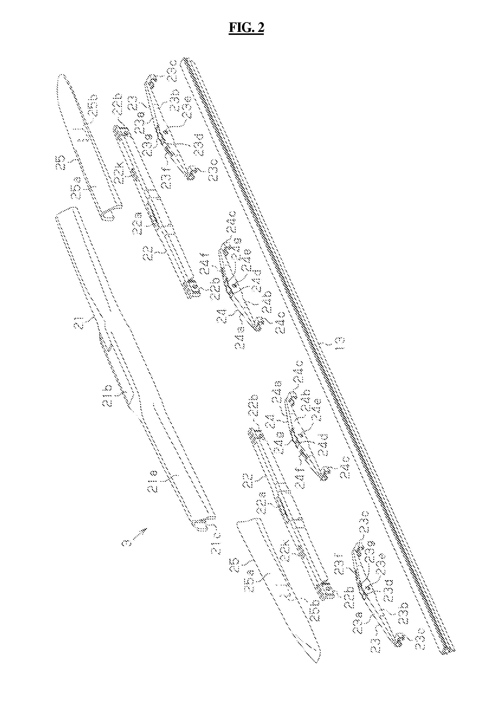
Reference Numerals11: wiper lever assembly12: backing13: blade rubber22, 51: secondary lever (upperlever)22b: insert connecting member22c: opposite lateral walls22d: end wall22e: insert tube22f, 51c: pivotal connecting pin (pivotal connecting part)22g, 51e: inclined surface22h: upper pressing arc portion (concave arc portion)23, 24, 52: yoke lever (lower lever)23a, 24a, 52a: top wall23b, 24b, 52b: lateral wall23c, 24c: grip portion23d, 24d: elongated aperture23e, 24e, 52c: pivotal connecting aperture (mating pivotal connecting part)23g, 24g: lower engaging arc portion (convex arc portion)51a: outer top wall51b: outer lateral wall51d: upper pressing arc portion (convex arc portion)52d: lower engaging arc portion (concave arc portion)

DETAILED DESCRIPTION

[0029]It is understood that the term “vehicle” or “vehicular” or other similar term as used herein is inclusive of motor vehicles in general such as passenger automobiles including sports utility vehicles (SUV), buses, trucks, va...


PUM


Abstract

Disclosed is a wiper lever assembly that includes upper and lower levers, a plurality of pivotal connecting parts that are pivotally coupled to a longitudinal end of the upper lever, and a plurality of mating pivotal connecting parts that are disposed on the lower lever. The assembly further includes an upper pressing arc portion disposed on the upper lever over the plurality of pivotal pressing parts. The upper pressing arc is in slidable contact with a lower engaging arc portion disposed on the lower lever. In addition, a radius of curvature of a concave arc of the upper pressing arc portion and the lower engaging arc portion is larger than that of a convex arc of the upper pressing arc portion and the lower engaging arc portion.

Description

BACKGROUND OF THE INVENTION[0001]1. Field of the Invention[0002]The present invention relates to a wiper lever assembly and a wiper blade.[0003]2. Description of the Related Art[0004]Among conventional wiper blades, a particular wiper blade is known which comprises a wiper lever assembly composed of an upper lever, having a lower lever coupled to the upper lever to pivotally connect the longitudinal center of the lower lever to a longitudinal end of the upper lever to to form a tournament shape, and a backing and a blade rubber, both of which are gripped by the wiper lever assembly.[0005]This type of conventional wiper lever assembly includes a lower lever, and an upper lever having an outer top wall and a pair of outer lateral walls (having an inverted U-shaped section) to substantially cover the lower cover, wherein the pair of outer lateral walls are elastically deformed to enlarge the area between the pair of outer lateral walls and the lower lever is fitted between the pair of ...

Claims


Application Information

Patent Timeline
IPC IPC(8): B60S1/34
CPCB60S1/3436B60S1/3801B60S2001/3815B60S1/3879B60S1/32B60S1/38B60S1/40
Inventor LEE, KI YOUNGLEE, DONG SOOLEE, IN KWANGCHA, IN GUELEE, HEUI GEONSHINICHIROU, AMANO
Owner DENSO CORP
Why Eureka
Try Eureka