Building wall with fluid ducts as energy barriers

a technology of building walls and fluid ducts, applied in photovoltaics, solar heat collectors with working fluids, solar heat collectors for particular environments, etc., can solve the problems of low-energy houses, usually have a substantial wall thickness, etc., and achieve the effect of preventing freeze damage in the outer absorption region and no space loss

Inactive Publication Date: 2013-10-24
KRECKE EDMOND D
View PDF0 Cites 11 Cited by
  • Summary
  • Abstract
  • Description
  • Claims
  • Application Information

AI Technical Summary

Benefits of technology

[0043]The fluid lines are preferably filled with a water-antifreeze mixture. Thus, freeze damage in the outer absorption regions can be prevented at extremely low temperatures.
[0044]The invention furthermore pertains to a method for producing a roof surface. In this case, carrier plates are fixed beneath the roof rafters. An insulating layer is initially bonded to or clamped on the carrier plates. Fluid-conducting lines are then applied on the insulating layer before another insulating layer is applied. Finally, the roof is provided with a roof covering. Consequently, a roof with an inventive fluid-conducting layer that can either be used as a temperature barrier layer and / or as an absorption layer can be very easily realized.
[0045]According to a preferred embodiment, the fluid-conducting lines are embedded in a sealing compound. Another insulating layer can be directly applied to the still liquid sealing compound so that the sealing compound and the insulating layer are connected together. This makes it possible very easily to construct a corresponding roof surface. However, it is not necessary to seal the fluid-conducting lines because they are protected from environmental influences by the roof covering. A thereby designed roof surface provides the particular advantage that it is arranged between the rafters of the roof such that no space is lost.
[0046]According to another refinement of the invention, another layer with fluid-conducting lines is applied which is preferably realized in the form of an absorption layer. This makes it possible to manufacture a roof surface with two layers of fluid-conducting lines, wherein the upper layer is used as an absorption layer and the lower layer is used as a temperature barrier layer.

Problems solved by technology

One disadvantage of known exterior walls of low-energy houses is that they usually have a substantial wall thickness.

Method used


Image

  • Building wall with fluid ducts as energy barriers
  • Building wall with fluid ducts as energy barriers
  • Building wall with fluid ducts as energy barriers

Examples


Embodiment Construction

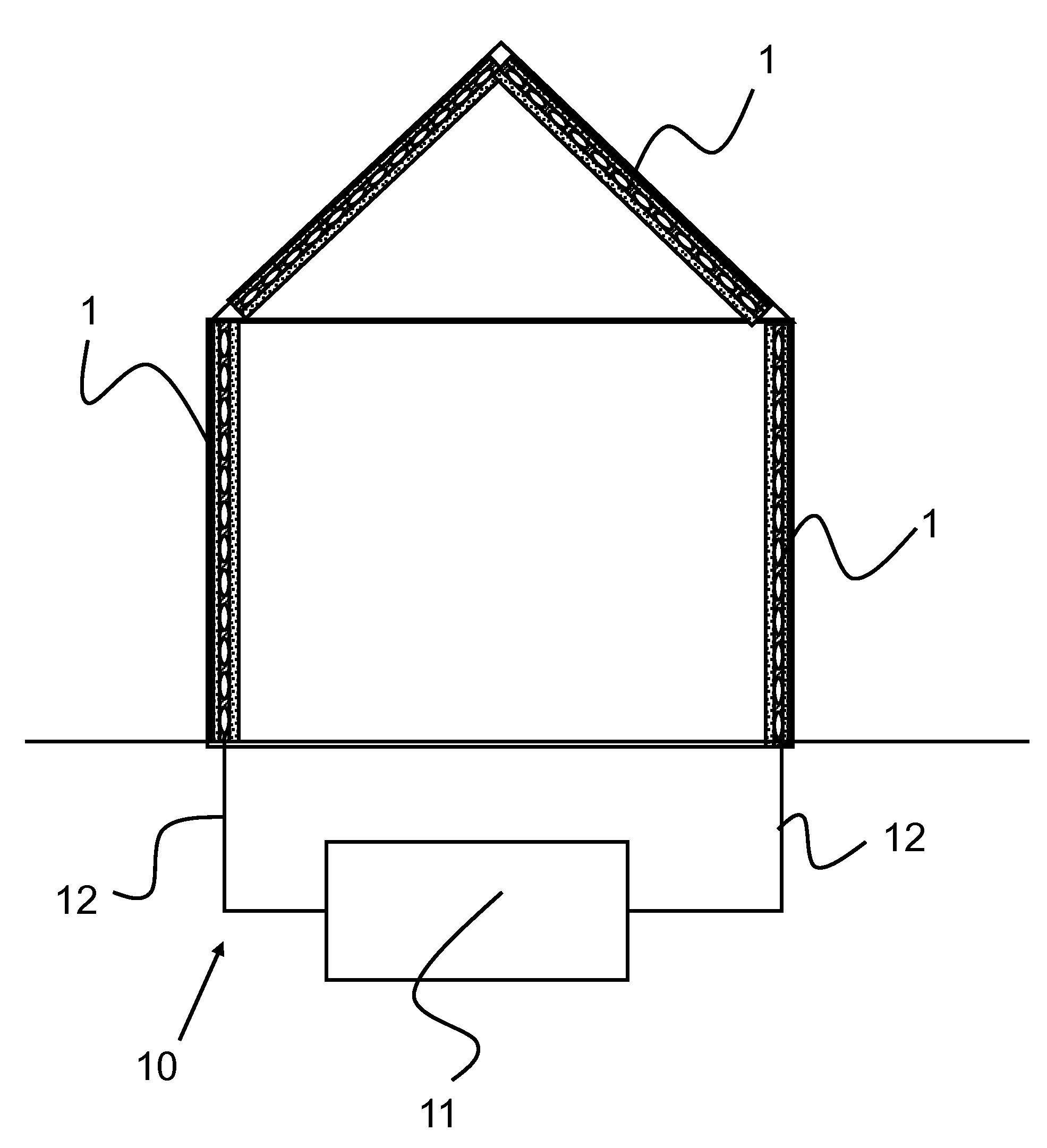
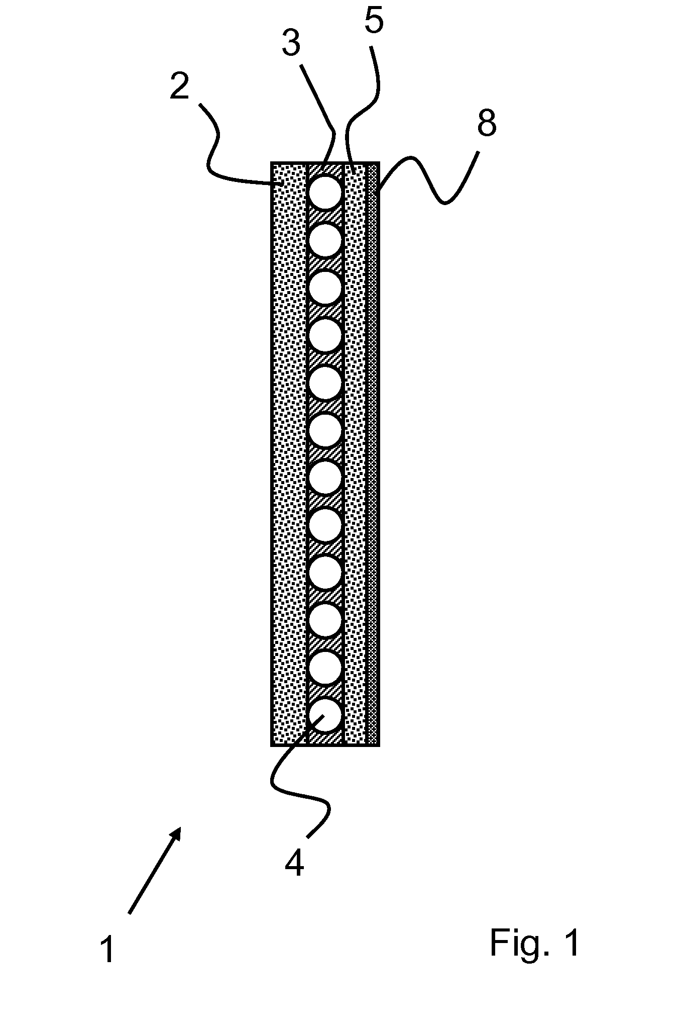
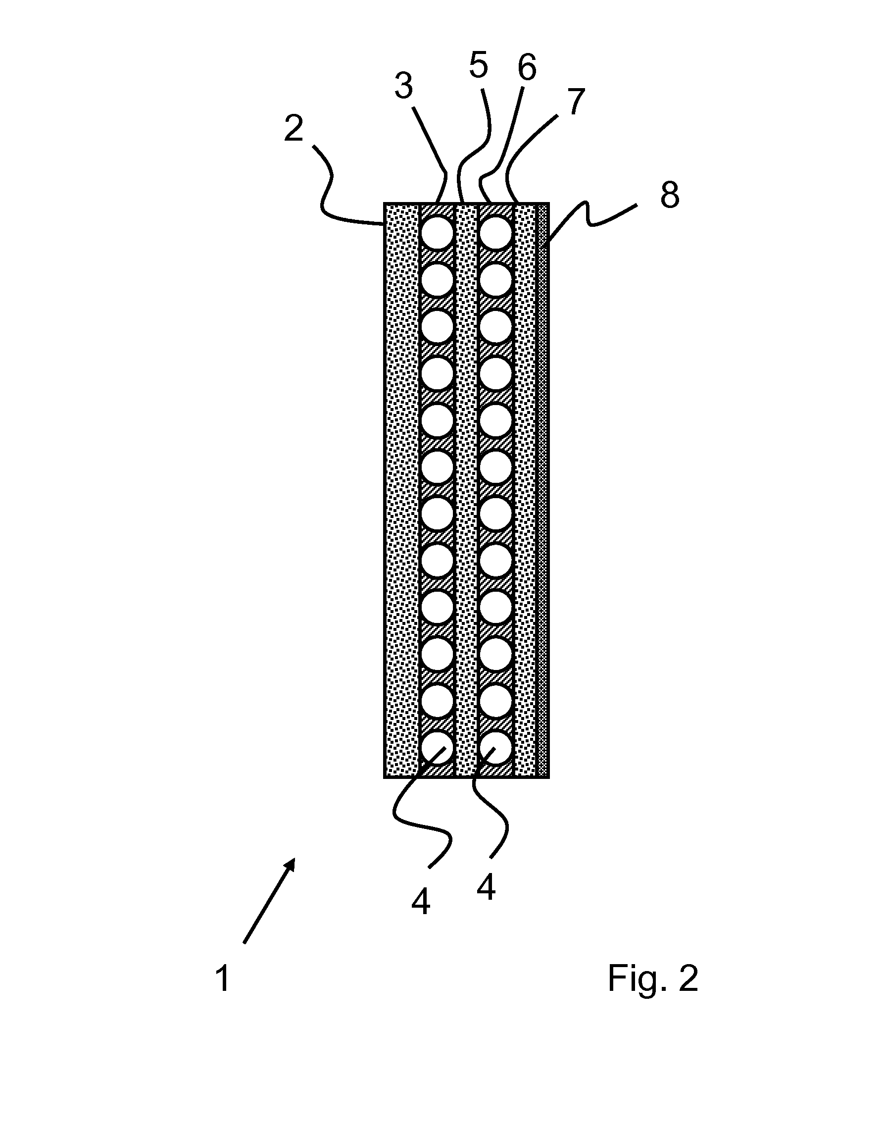
[0054]FIG. 1 schematically shows an inventive wall or roof surface element 1 that is realized in the form of a modular element suitable for use in the construction of prefabricated buildings as well as the modernization of old buildings.

[0055]The wall element 1 comprises an inner insulating layer 2 and an outer insulating layer 5. A temperature barrier layer 3 is arranged between the inner insulating layer 2 and the outer insulating layer 5. The temperature barrier layer 3 comprises fluid lines 4 through which a water-antifreeze mixture can circulate. An exterior layer 8 provided on the outer side comprises a fiberglass mat covered with plaster in order to protect the wall or roof surface element 1 from weather effects. According to the invention, the wall or roof surface element is extremely thin, i.e., it is realized with a thickness of less than 35 cm. Such a thin exterior wall makes it possible to achieve very high efficiencies with respect to the mean annual energy gain. As soo...


PUM


Abstract

The invention relates to a wall or roof surface element comprising a temperature barrier layer and an extremely thin external insulating layer. Alternatively, an absorption layer can also be provided on the external side. A building fitted with said type of elements has a positive energy balance.

Description

CROSS-REFERENCE TO RELATED APPLICATIONS[0001]This application is a Continuation of and claims priority to U.S. patent application Ser. No. 11 / 996,255 with a 371 entry date of Jan. 18, 2008, which is the 371 filing of International Application Serial Number PCT / EP2006 / 000182 filed on Jan. 11, 2006, which in turn claims priority to German Application Number DE 10 2005 034 970.6 filed on Jul. 22, 2005. Furthermore, U.S. patent application Ser. No. 11 / 996,255 is incorporated herein by reference.FIELD OF THE INVENTION[0002]The invention pertains to a building wall with fluid ducts as temperature barriers and to a roof surface with fluid ducts as temperature barriers, as well as to a method for manufacturing a roof surface according to the invention.BACKGROUND OF THE INVENTION[0003]Building walls with fluid ducts that act as thermal barriers are known. For example, German OLS DE 298 04 095, entitled “Low-energy House,” discloses a building wall with a core zone that features fluid lines. ...

Claims


Application Information

Patent Timeline
Patent Type & Authority Applications(United States)
IPC IPC(8): F24J2/24F24S10/70
CPCF24J2/243E04B7/22E04C2/525Y02B10/20Y02E10/44F24S20/67F24S20/66F24S10/73Y02A30/60
Inventor KRECKE, EDMOND D.
Owner KRECKE EDMOND D
Why Eureka
Try Eureka