Sawing machine and cutting method of a sawing machine

a sawing machine and cutting technology, applied in the field of sawing machines, can solve the problems of inability to reduce the position of the last cutting, the side support of the sawing blade cannot close the workpiece further, and the bending, vibration and noise of the sawing blade occurred between the position so as to prolong the life reduce the cutting amount. , the effect of reducing the bending and vibration of the sawing blad

Inactive Publication Date: 2013-10-24
WASHIO JUNKO
View PDF11 Cites 11 Cited by
  • Summary
  • Abstract
  • Description
  • Claims
  • Application Information

AI Technical Summary

Benefits of technology

[0024]According to above aspects of the invention, even in the case of cutting a bulged work-piece such as a round material and a hexagonal material with a sawing machine, the saw blade is configured to be supported along the external side of the work-piece by the saw blade side supports between the positio

Problems solved by technology

However, in the cutting devices described above, in the process for cutting a bulged work-piece such as a round material or a hexagonal material etc., the saw blade side supports move apart from the cutting surface of the work-piece toward the left and right between the position of the saw blade passing the center point of the work-piece and the position of the last cutting, therefore, the bending, vibration and noise of the saw blade occurred between the position of the saw blade passing the center point of the work-piece and the position of the last cutting are unable to be decreased.
Particularly, in a band saw machine, the saw blade back support and the saw blade

Method used


Image

  • Sawing machine and cutting method of a sawing machine
  • Sawing machine and cutting method of a sawing machine
  • Sawing machine and cutting method of a sawing machine

Examples


embodiment 1

[0050]An embodiment relating to the present invention will be described in detail with reference to the accompanying drawings hereinafter.

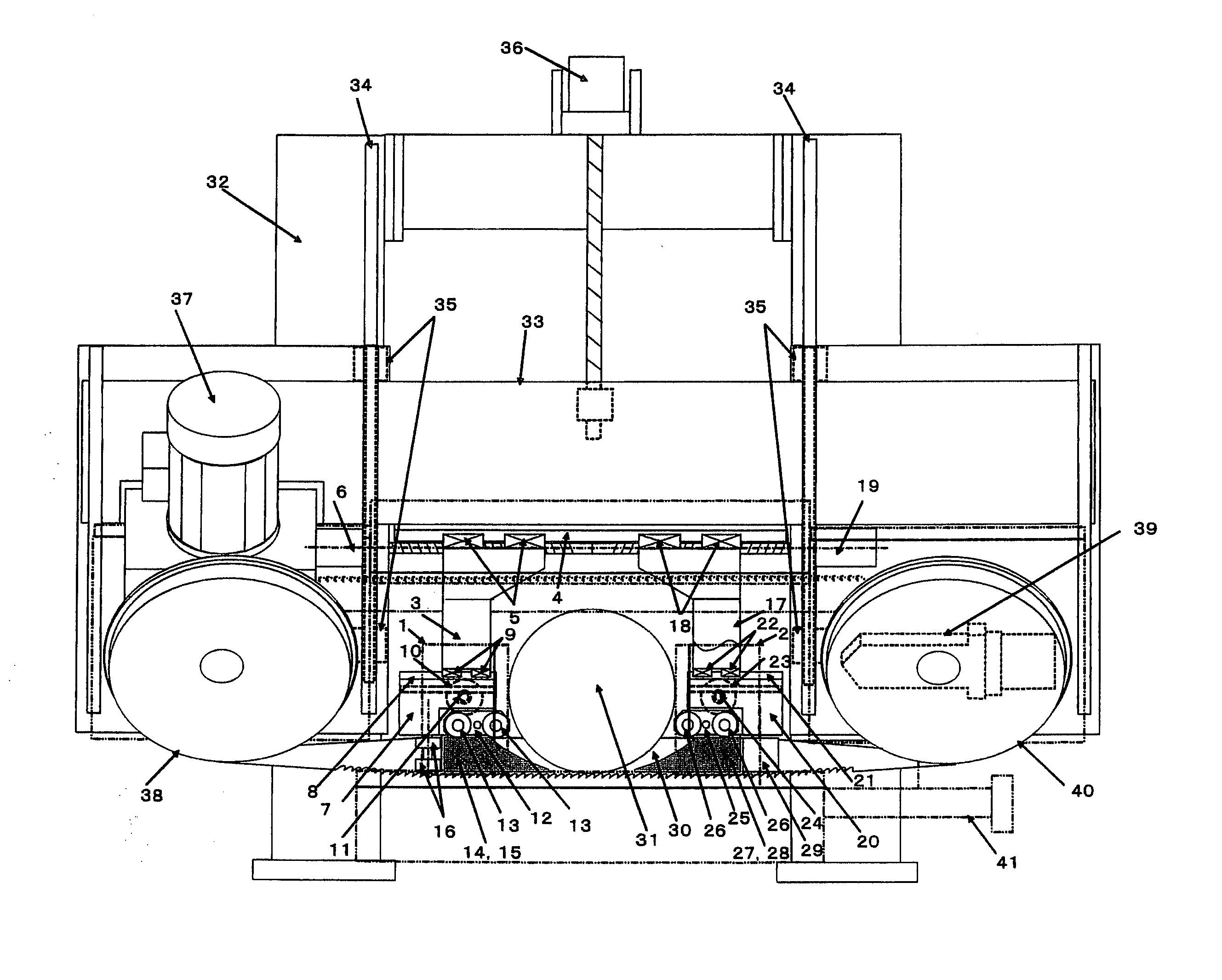
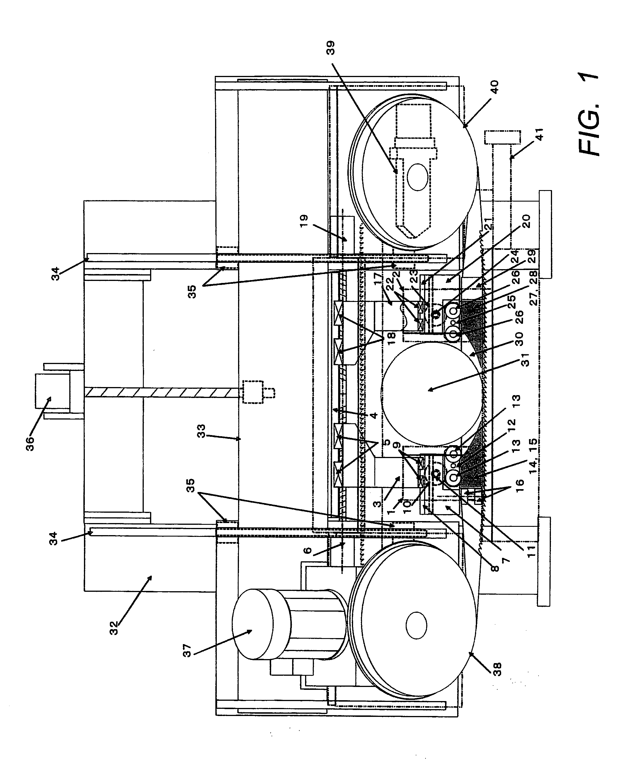
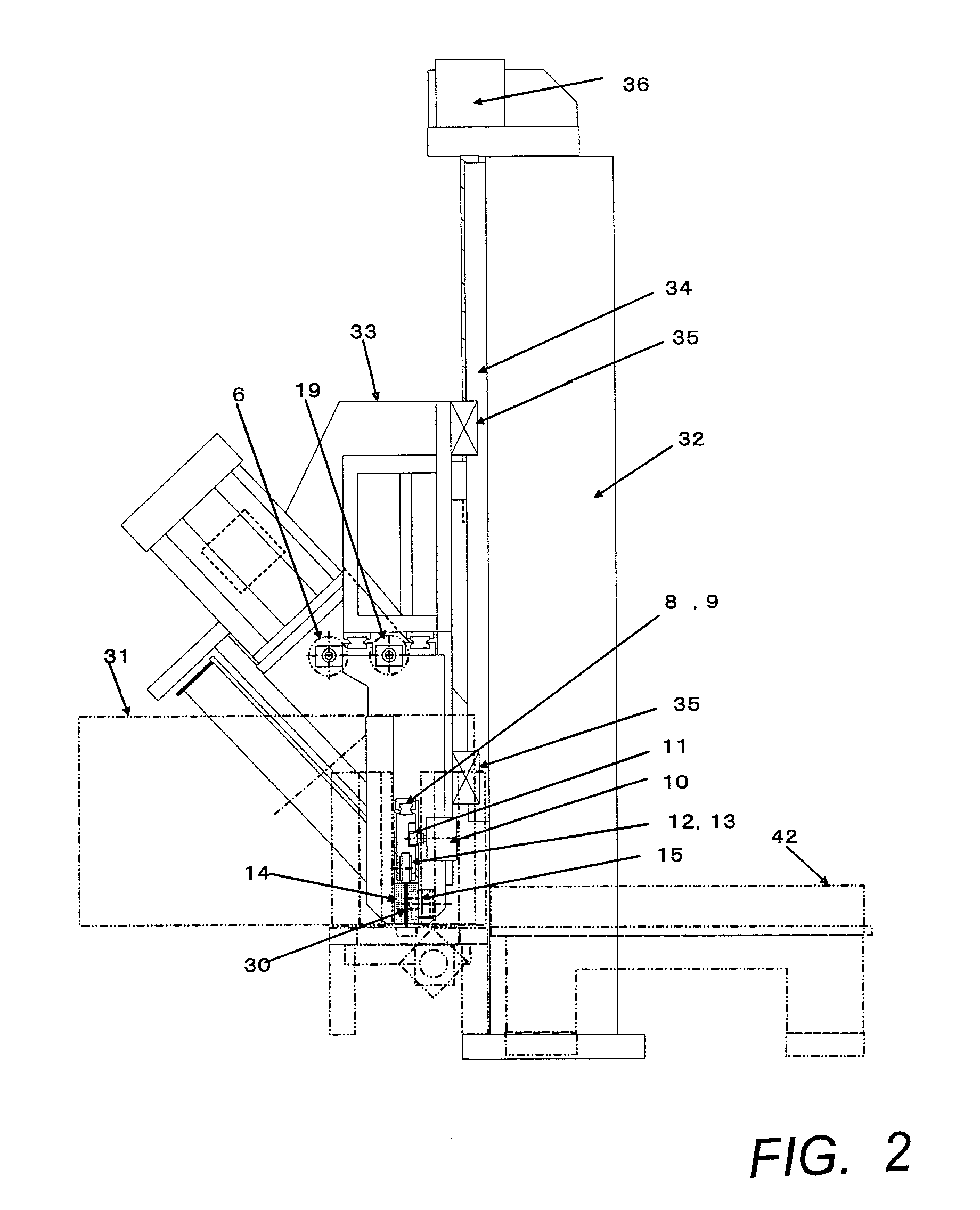
[0051]FIG. 1 to FIG. 3 show embodiment 1 in which the saw blade support device according to the present invention is applied to a band saw machine. FIG. 1 is a front view of the band saw machine relating to embodiment 1, FIG. 2 is a side view and FIG. 3 is a plan view.

[0052]The band saw machine includes a feeding device (not shown in figure) for carrying work-piece 31, a body vice device for fixing the work-piece 31 and a cut processing portion for cutting the work-piece 31. The feeding device generally includes a roller table equipped with a plurality of free rotating rollers and a feeding vice unit for carrying the work-piece on the roller table to the saw blade position. The body vice device comprises a body fixed vice 1 and a body moveable vice 2 for clamping and fixing the work-piece 31. Specifically, as shown by the chain line in FIG. 1, the...

embodiment 2

[0082]The embodiment 2 in which the saw blade support device relating to the present invention is applied to a circular saw machine will be described in detail with reference to FIGS. 14A-B and FIGS. 15A and 15B-D. FIG. 14A is a plan view of a circular saw machine relating to the embodiment 2 with a saw blade cover of the saw frame portion opened 180° and FIG. 14B is a front view.

[0083]The circular saw machine includes a feeding device (not shown in figure) for carrying work-piece 31, a body vice device for fixing the work-piece 31 and a cut processing portion for cutting the work-piece 31. The feeding device includes a roller table equipped with a plurality of free rotating rollers and a feeding vice unit for carrying the work-piece on the roller table to the saw blade position. The body vice device comprises a body fixed vice 1 and a body moveable vice 2 for clamping and fixing the work-piece. Specifically, as shown by chain line in FIG. 14, the work-piece 31 is fixed by clamping ...


PUM

PropertyMeasurementUnit
Lengthaaaaaaaaaa
Shapeaaaaaaaaaa
Widthaaaaaaaaaa

Abstract

Traditionally, in order to avoid interfering with a work-piece such as a round material and an hexagonal material etc., an insert plate used as a saw blade side support of a band saw machine or a circular saw machine is provided at a position apart from the cutting site after passing the maximum cutting width, which results in the bending, vibration and noise of the saw blade, thereby decreasing the life of the saw blade. This problem is solved with two insert plates located at two positions on left and right of a work-piece to support the saw blade in a manner of moving them closing to the work-piece along the external shape of the work-piece from the cutting start and after passing the maximum cutting width by enabling them to move along the external side of the work-piece, therefore, one side of the insert plates takes a tapered shape so as to get into under the work-piece.

Description

FIELD OF THE INVENTION[0001]The present invention relates to a sawing machine, in particular to a saw blade support device of a band saw machine or a circular machine for cutting a work-piece by means of revolving or rotating the saw blade. More particularly, it relates to a technique which enables a saw blade side support device for supporting the saw blade from both sides to move along the shape of external side of a work-piece.BACKGROUND OF THE INVENTION[0002]A band saw machine or a circular saw machine for cutting a work-piece by means of revolving or rotating a saw blade has been used as a device for cutting round materials and angular materials so far.[0003]For an example, on a horizontal band saw machine, a work-piece is clamped and fixed by a body fixed vice and a body movable vice, and the work-piece is cut by an endless saw blade which is winded on a driving wheel and a driven wheel provided on a saw frame enabled to move up and down, by revolving the endless saw blade and...

Claims


Application Information

Patent Timeline
IPC IPC(8): B23D59/00B26D5/02
CPCB23D59/002B26D5/02B23D47/005B23D55/082Y10T83/04Y10T83/538
Inventor WASHIO, ISOMI
Owner WASHIO JUNKO
Why Eureka
Try Eureka