Liquid leakage prevention device, liquid leakage prevention method, and liquid cooling system
a technology of liquid leakage prevention and liquid cooling system, which is applied in the direction of lighting and heating apparatus, instruments, and semiconductor/solid-state device details, etc., can solve the problems of liquid leaching from a connection portion of the joint, affecting the reliability of an electronic device, and inability to prevent internal refrigerant liquid from being leaked to the external
- Summary
- Abstract
- Description
- Claims
- Application Information
AI Technical Summary
Benefits of technology
Problems solved by technology
Method used
Image

Examples
first embodiment
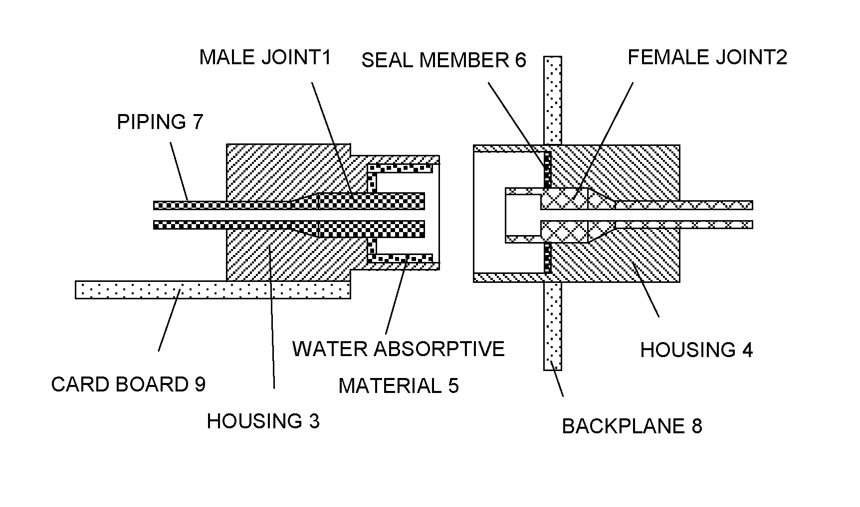
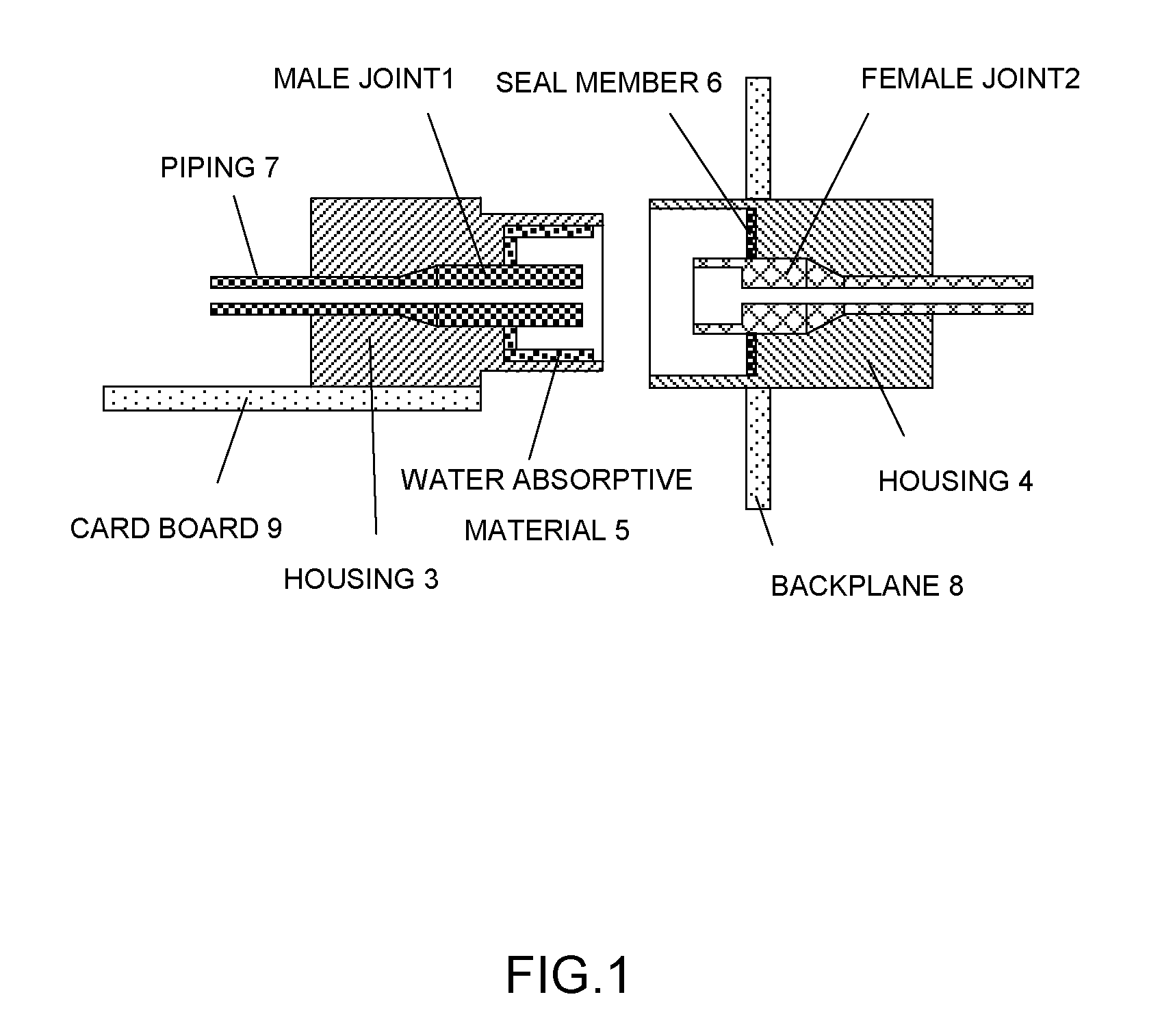
[0089]FIG. 1 is a cross-sectional view illustrating a structure of a joint according to a first embodiment of the invention, which illustrates a state before a male joint 1 and a female joint 2 are fitted to each other. The joint according to this embodiment includes the male joint 1 and the female joint 2, and housings 3 and 4 that fix those joints to each other. Those housings 3 and 4 include a lock mechanism (not shown) for holding a state where the male joint 1 and the female joint 2 are fixed to each other. A water absorptive material 5 such as a water absorptive polymer is disposed on an inner wall of the housing 3 of the male joint 1, and a seal member 6 such as a rubber packing is disposed on an inner wall of the housing 4 of the female joint 2. In this example, the water absorptive material 5 (water absorptive polymer, etc.) is made of, for example, a material processed into a sheet shape, and has a size or volume as large as at least a liquid having the same volume as that...
second embodiment
[0103]FIG. 11 is a cross-sectional view illustrating a structure of a joint according to a second embodiment of the invention.
[0104]Incidentally, as another means for detecting the liquid leakage, there is proposed a method stated below.
[0105]Referring to FIG. 11, a depression is formed in the inner wall of the housing 3 of the male joint 1, and a pressure sensor 111 is provided within the depression. The pressure sensor 111 is connected to a liquid leakage detector circuit 113 mounted on the card board 9 by a cable 112 passing through the housing 3, and monitors a pressure value applied to the pressure sensor 111. Also, a water swellable water stop material that can absorb at least a liquid of the same volume as that of the space confined in the housing 3 is installed on the inner wall of the housing 3 as the water absorptive material 5.
[0106]FIG. 12 is a cross-sectional view illustrating a behavior at the time of leaking the liquid in the joint structure according to the second em...
third embodiment
[0111]FIG. 14 is a cross-sectional view illustrating a structure of a joint according to a third embodiment of the invention.
[0112]Further, as another means for detecting the liquid leakage, a liquid leakage sensor 141 shown in the figure may be used. Referring to FIG. 14, the water absorptive material 5 (water absorptive polymer, etc.) is disposed on the inner wall of the housing 3 of the male joint 1, and the liquid leakage sensor 141 is installed on the water absorptive material 5 (water absorptive polymer, etc.). There are several types of liquid leakage sensors 141, and as the most general type, for example, paper is wrapped around each of two conductive wires, and the two conductive wires are bundled together, and installed in a place where the liquid leakage is sensed. If the liquid is leaked, water penetrated into paper reduces an electric resistance between the two conductive wires, and the reduction of the electric resistance is electrically sensed to output an alarm. If n...
PUM
 Abstract
Description
Claims
Application Information
 - R&D
- Intellectual Property
- Life Sciences
- Materials
- Tech Scout
- Unparalleled Data Quality
- Higher Quality Content
- 60% Fewer Hallucinations
Browse by: Latest US Patents, China's latest patents, Technical Efficacy Thesaurus, Application Domain, Technology Topic, Popular Technical Reports.
© 2025 PatSnap. All rights reserved.Legal|Privacy policy|Modern Slavery Act Transparency Statement|Sitemap|About US| Contact US: help@patsnap.com