
Methods for measuring and transmitting downlink signals and apparatuses therefor

a technology of downlink signal and method, applied in the field of wireless communication system, can solve the problems of low transmission efficiency and overall system performance degradation

Active Publication Date: 2013-10-24
LG ELECTRONICS INC +1
View PDF5 Cites 66 Cited by
  • Summary
  • Abstract
  • Description
  • Claims
  • Application Information

AI Technical Summary

Benefits of technology

The present invention relates to an apparatus and method for improving the performance of low-layer user equipments (UEs) located at the edge of a cell in a cellular mobile communication system. The apparatus includes an antenna system that supports multiple beam direction patterns. The proposed method involves using the antenna system to improve the signals received by the UEs and reduce interference from neighboring cells. This can lead to better performance for low-layer UEs located at the cell edge. The method also includes a switching mechanism to allow the UEs to transition to an idle state in certain subframes to further reduce interference and improve signal quality. The technical effects of the invention include improved performance of low-layer UEs and reduced interference from neighboring cells.

Problems solved by technology

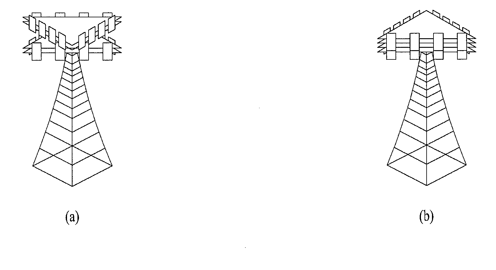
In a conventional wireless communication system providing a service using a 3-sector beam direction pattern in each cell, User Equipments (UEs) in the vicinity of the eNB have high transmission efficiency, whereas UEs at a cell edge have low transmission efficiency due to Inter-Cell Interference (ICI) and this is a main cause of performance degradation of the overall system.

Method used


Image

  • Methods for measuring and transmitting downlink signals and apparatuses therefor
  • Methods for measuring and transmitting downlink signals and apparatuses therefor
  • Methods for measuring and transmitting downlink signals and apparatuses therefor

Examples


Embodiment Construction

[0050]Reference will now be made in detail to the preferred embodiments of the present invention, examples of which are illustrated in the accompanying drawings. The detailed description set forth below in connection with the appended drawings is intended as a description of exemplary embodiments and is not intended to represent the only embodiments in which the concepts explained in these embodiments can be practiced. The detailed description includes details for the purpose of providing an understanding of the present invention. However, it will be apparent to those skilled in the art that these teachings may be implemented and practiced without these specific details.

[0051]The following technique, apparatus and system is applicable to various wireless multiple access systems. For convenience of description, assume that the present invention is applied to 3GPP LTE(-A). However, the technical features of the present invention are not limited thereto. For example, although the follo...


PUM


Abstract

A method in which a User Equipment (UE) measures a downlink signal in a wireless communication system is disclosed. The method includes receiving information about a Beam Direction Pattern (BDP) of the downlink signal and measuring the downlink signal based on the information about the BDP. The information about the BDP includes an index of a subframe in which the downlink signal is to be transmitted using a specific BDP and includes an identifier (ID) of the specific BDP. The BDP of the downlink signal is switched according to the subframe index based on the information about the BDP.

Description

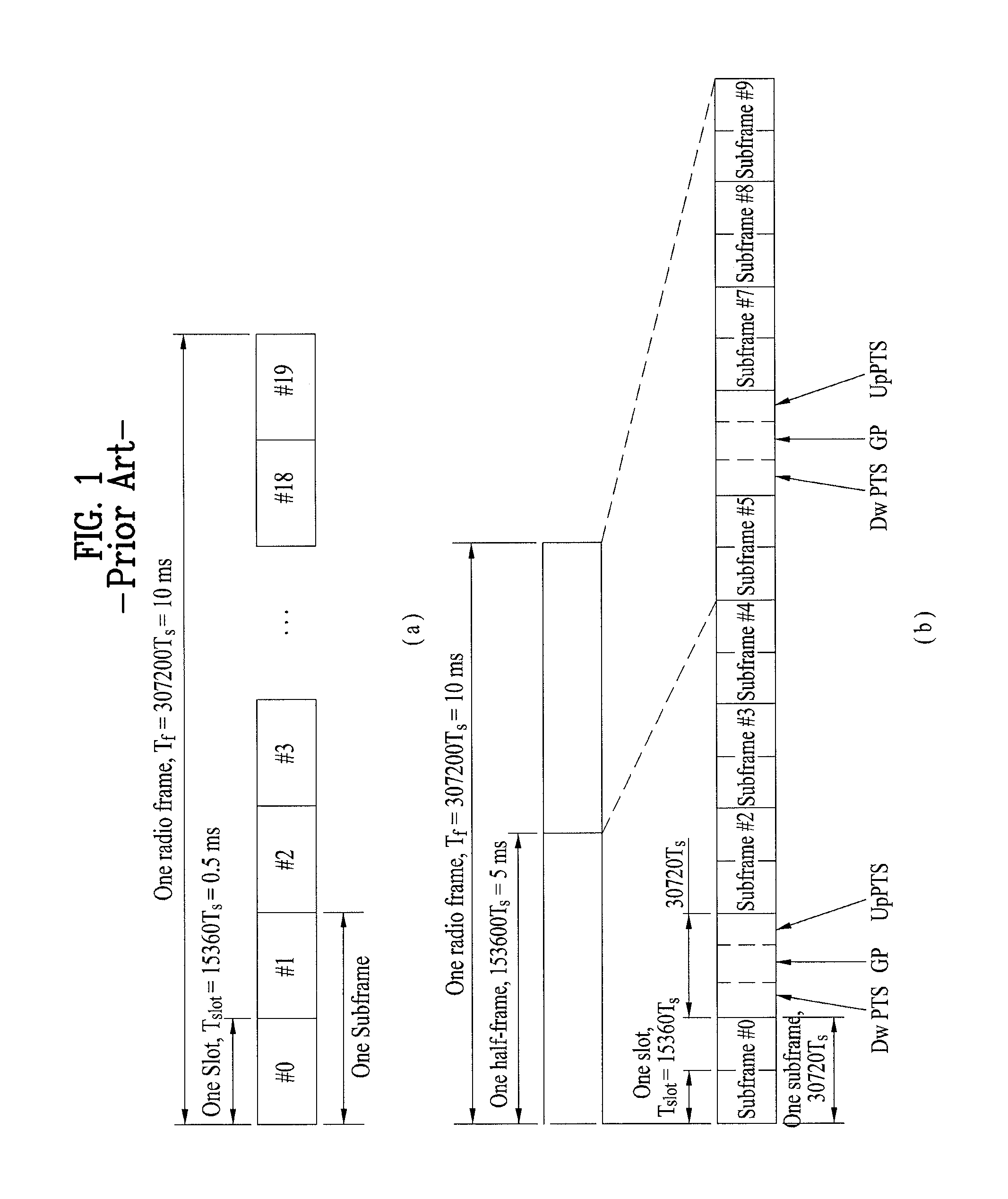
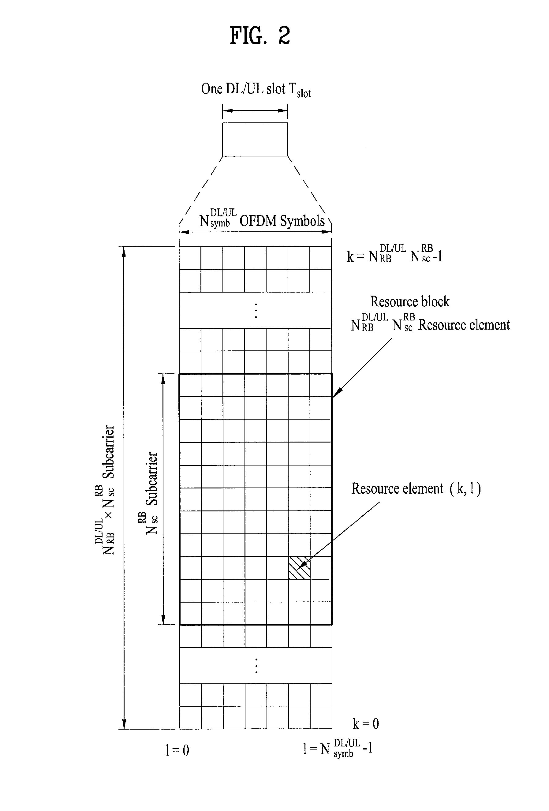
[0001]This application claims the benefit of U.S. Provisional Application No. 61 / 637,795, filed on Apr. 24, 2012, which is hereby incorporated by reference as if fully set forth herein.BACKGROUND OF THE INVENTION[0002]1. Field of the Invention[0003]The present invention relates to a wireless communication system, and more particularly, to a method for measuring downlink signals, a method for transmitting downlink signals, and apparatuses therefor.[0004]2. Discussion of the Related Art[0005]A model of a conventional 3-sector wireless communication system is illustrated in FIG. 8. An overall system includes a plurality of cells and each cell further divided into sectors is equipped with a macro eNB which is in charge of signal transmission. In a conventional wireless communication system providing a service using a 3-sector beam direction pattern in each cell, User Equipments (UEs) in the vicinity of the eNB have high transmission efficiency, whereas UEs at a cell edge have low transm...

Claims


Application Information

Patent Timeline
Patent Type & Authority Applications(United States)
IPC IPC(8): H04W24/02
CPCH04W24/02H04W16/28H04B7/0665H04B7/0695H04L5/001H04L5/0023H04L5/0048H04L5/0053H04L5/1469H04W72/23H04J11/0053
Inventor PARK, JONGHYUNSHIN, SUKHOKIM, JAEWONLEE, DONGHYUNKIM, KIJUNSUNG, WONJIN
Owner LG ELECTRONICS INC
Learn More