Communication apparatus and communication method
Active Publication Date: 2013-10-24
SUN PATENT TRUST
4 Cites 107 Cited by
AI-Extracted Technical Summary
Problems solved by technology
However, in the transmission system of LTE Rel. 8, an effect of reducing interference with other cells and a decrease in the frequency usage efficiency through th...
View moreMethod used
[0080]Next, the UE feedback-transmits the selected extended PMI (worst PMI list) to the NodeB #0 (serving cell) as a control signal according to a predetermined transmission processing sequence such as a modulation processing. In addition, the UE may additionally feed back the optimal PMI (best PMI) in the serving cell. (At this time, the UE may feed back a cell ID of another cell, which corresponds to the identified extended PMI, together with the extended PMI information. Therefore, the NodeB #0 (serving cell), which is a feedback destination, may recognize which cell (node) generates other-cell interference with which UE. Therefore, this may be used for frequency scheduling (allocation of a plurality of UEs to a frequency resource) within the NodeB #0 (serving cell), such that a multi-user diversity based on the frequency resource allocation within the NodeB #0 (serving cell) may be improved and thereby a cell throughput may be improved.). In addition, the optimal PMI (for example, best PMI) between the NodeB #0 and the serving UE may be additionally selected.
[0084]The extended PMI list storing unit (for other nodes) 129 generates an extended PMI list that is fed back from the plurality of UEs in the serving cell for each frequency resource (for example, in PRB units). For example, the extended PMI list storing unit 129 generates an extended PMI (worst PMI list) that is expected not to be used by other cells (whose use is restricted, prohibited, and not encouraged). For example, to reduce other-cell interference from the NodeB #1 (non-serving cell) that is a neighbor cell of the NodeB #0 to the NodeB #0 (serving cell), the extended PMI list storing unit 129 generates an extended PMI list in frequency resource (PRB) units, in which use in the neighbor cell NodeB #1 is restricted (prohibited, and not encouraged) (refer to FIG. 4).
[0086]In addition, the extended PMI list shown in FIG. 4 may be individually generated for each of other cells on the basis of the cell ID that is fed back together with the extended PMI, or may be generated with one list by collecting a plurality of cells among other cells other than the serving cell. In the case of creating one list by collecting the plurality of cells among other cells other than the serving cell, complexity and computation of the NodeB #0 may be reduced.
[0110]As described above, according to the transmission system related to this embodiment, the communication apparatus 100 autonomously selects and notifies only necessary minimum precoding (beamforming) information of the UE that performs the CoMP among the plurality of cells in a specific frequency resource in response to the transmission signal power information or the like, such that it is possible to reduce overhead related to precoding (beamforming weight (for example, the number of PMI lists)) information that is notified over the backhaul while maintaining the ICI reduction effect due to DL coordinated CoMP (CB, JP, or the like) among a plurality of nodes.
[0111]In addition, according to the transmission system related to this embodiment, since the communication apparatus 100 performs notification of only the precoding (beamforming) information with respect to a UE that is present at the cell edge, the overhead is reduced, and the degree of freedom of the scheduling in a frequency domain and a spatial domain among a plurality of cells, that is, a multi-user diversity effect among the plurality of cells, which are based on the allocation of the UE with respect to the frequency resource and the spatial resource among the plurality of cells, may be also maintained.
[0154]Therefore, in regard to the transmission system related to the second modification example, the communication apparatus of the second modification example related to the first embodiment increases coordination CB/JP information only in a specific frequency resource in which large interference may be applied to other cells with high probability when seen from the serving node (large interference from other cells when seen from other nodes), such that the ICI reduction effect due to the coordination ICIC among a plurality of nodes may be further improved.
[0186]In this manner, to reduce other-cell interference, the coordinated beamforming (CB) sets the precoding (beamforming) information, which is expected not to be used by other cells (whose use is suppressed, prohibited, and restricted), as useful information. On the other hand, to reduce other-cell interference, the joint-processing (JP) set the precoding (beamforming) information, which is encouraged to be used by other cells, as useful information. Therefore, in each of the CS, CB, and JP, appropriate precoding (beamforming) may be performed between coordinated cells.
[0201]For example, in a case where the UE that is an object of the CoMP and the non-CoMP UE are effectively used with a frequency resource in a system band, generally, the number of them is different in each case (the number of CoMP UEs
[0206]In addition, in regard to a method of performing notification of information of the sub-band number and the bitmap representing whether or not the notification of the PMI in th...
View moreBenefits of technology
[0031]According to the communication apparatus and the communication method related to the invention, it is possible to reduce overhead related to precoding information (for example, PMI)...
View moreAbstract
Overhead related to precoding (beamforming weight) information to be notified over a backhaul may be reduced while maintaining an ICI reduction effect by coordinated CoMP among a plurality of nodes. A communication apparatus of the invention includes a reception unit that receives precoding information from user equipment, a selection unit that variably controls an amount of the precoding information, which is to be notified to another communication apparatus via a backhaul, in response to positions of frequency resources, and a transmission unit that transmits the precoding information to the other communication apparatus in accordance with the amount of the precoding information controlled by the selection unit.
Application Domain
Technology Topic
Image
Examples
- Experimental program(9)
Example
First Embodiment
[0062]A first embodiment will be described in detail. This embodiment has the following characteristics (a) to (c).
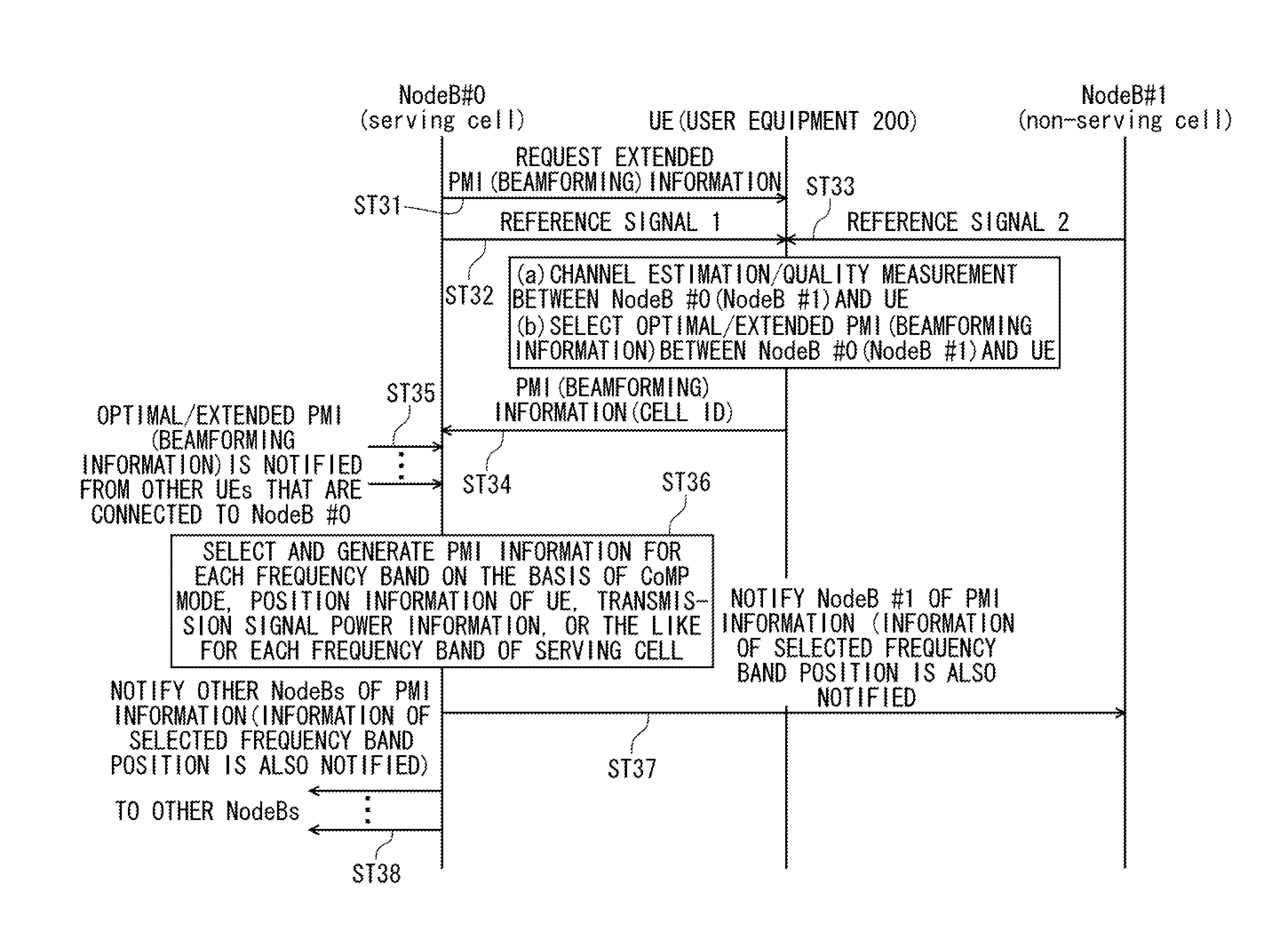
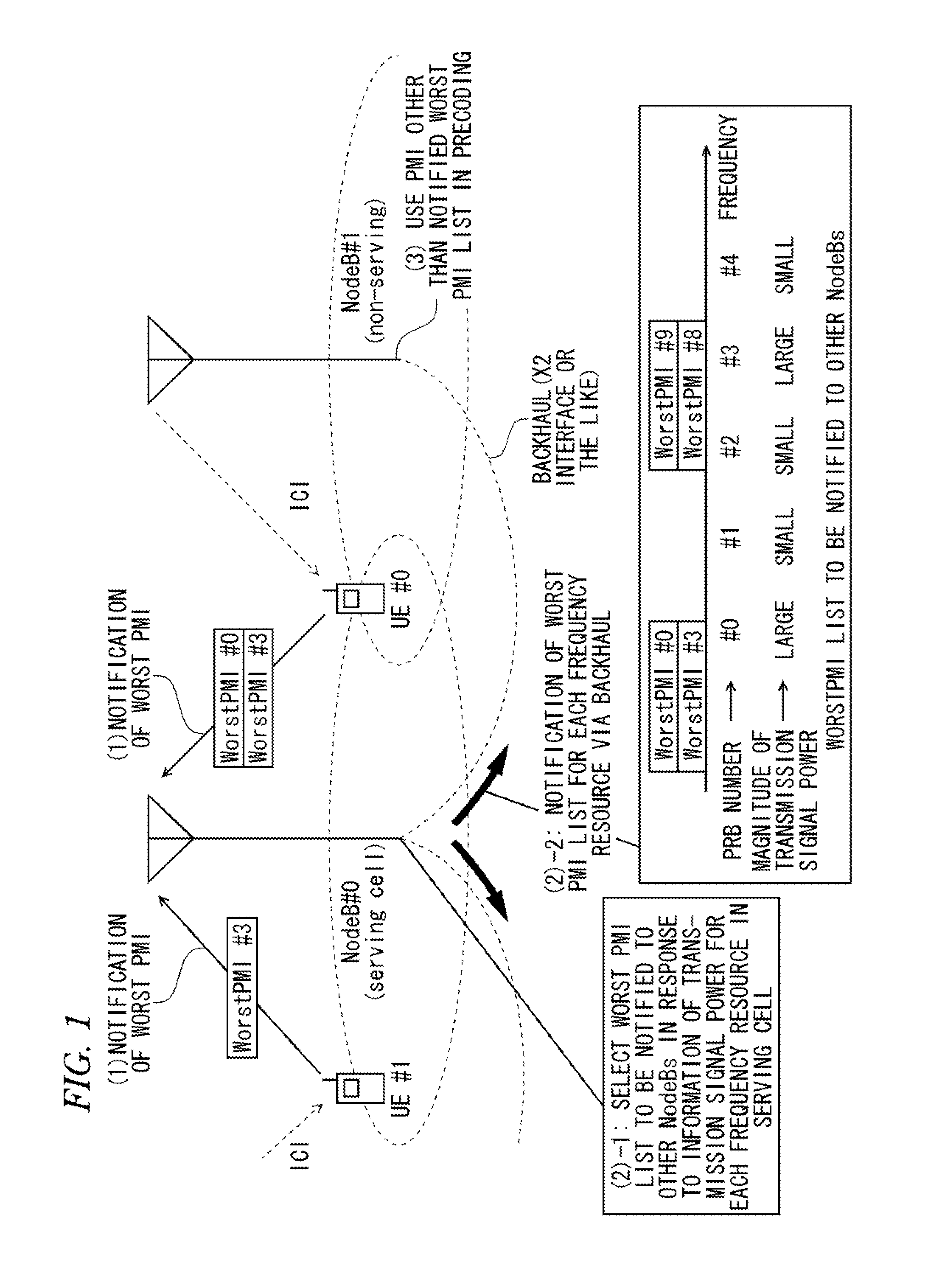
[0063](a) An amount of precoding (beamforming) information (for example, the number of PMI lists) that is to be notified to other nodes via the backhaul is variably controlled in response to a resource position of a frequency domain, and this information and information of a selected frequency resource position are notified to other nodes.
[0064](b) Information of a magnitude of future transmission power (density), a magnitude of (normalized) transmission signal energy (density), or good or bad of a communication quality for each frequency resource in the serving cell, and the amount of the precoding (beamforming) information (for example, the number of PMI lists) at the frequency resource position are correlated with each other.
[0065](c) As the future transmission power (density) or (normalized) transmission signal energy (density) for each frequency resource in the serving cell is large (or small), or as the communication quality becomes better (or worse) for each frequency resource in the serving cell, the amount of precoding (beamforming) information (for example, the number of PMI lists) at a corresponding resource is made to increase (or decrease).
[0066]FIG. 1 shows a conceptual diagram of a transmission system according to the first embodiment. FIG. 2 shows a block diagram of a communication apparatus (base station (NodeB)) 100 in the transmission system according to this embodiment. In addition, FIG. 3 shows a diagram illustrating a control sequence in the transmission system shown in FIG. 1.
[0067]In the transmission system shown in FIG. 1, a NodeB #0 (a serving cell) selects an amount of precoding (beamforming) information (for example, the number of worst PMI lists), which is notified to other nodes, in response to information of transmission signal power for each frequency resource in the serving cell ((2)-1 in the drawing), and notifies NodeB #1 (non-serving cell) that is another node of the amount of the precoding (beamforming) information for each frequency resource via a backhaul (for example, an X2 interface). In this manner, the NodeB #0 (serving cell) performs the ICIC of a frequency domain and a spatial domain.
[0068]In FIG. 1, as an amount of precoding (beamforming) information for each frequency band, a worst PMI list is shown. For example, in a physical resource block (PRB) number of #0, since transmission signal power is large, two worst PMI #0 and worst PMI #3 are shown in the worst PMI list.
[0069]The communication apparatus (base station (NodeB)) 100 shown in FIG. 2 includes a reception processing unit 101, a control information extracting unit 103, an extended PMI list storing unit (for a serving node) 105, a precoding weight determining unit 107, a data information transmission processing unit 109, a control information transmission processing unit 111, a reference signal transmission processing unit 113, a radio transmission processing unit 119, a radio reception processing unit 125, a control information extracting unit 127, an extended PMI list storing unit (for other nodes) 129, an extended PMI list selecting unit 131, a control information generating unit 133, a transmission processing unit 135, and a transmission and reception antenna 137. Hereinafter, in this embodiment, it is assumed that the communication apparatus 100 is located in the NodeB #0 (serving cell).
[0070]
[0071]The NodeB #0 (serving cell) receives an extended PMI feedback request signal from an upper layer, and inputs this information to the control information transmission processing unit 111. It is assumed that this extended PMI (beamforming) request is notified, for example, with signaling of a higher layer.
[0072]The control information transmission processing unit 111 converts the extended PMI feedback request signal into a binary bit sequence, performs a predetermined transmission signal processing such as channel encoding and modulation, and outputs the resultant signal to the radio transmission processing unit 119.
[0073]In addition, the reference signal transmission processing unit 113 performs a predetermined transmission signal processing according to a reference signal transmitting request, and outputs the generated reference signal to the radio transmission processing unit 119. As a kind of reference signal, CRS (Cell Specific Reference Signal), CSI-RS (Channel State Information Reference Signal), DIVERS (De-Modulation Reference Signal), and US-RS (User Specific Reference Signal) may be exemplified.
[0074]The radio transmission processing unit 119 performs a radio transmission processing such as D/A conversion, amplification, and up-conversion with respect to a signal input from the control information transmission processing unit 111, and transmits the signal subjected to the radio transmission processing toward a UE as an extended PMI (beamforming) request signal via the transmission and reception antenna 137. In addition, the radio transmission processing unit 119 performs the same processing with respect to a reference signal input from the reference signal transmission processing unit 113 and transmits the processed reference signal via the transmission and reception antenna 137.
[0075]
[0076]Here, an operation of user equipment (UE) 200 that is connected to the NodeB #0 will be described. Hereinafter, the user equipment 200 is sometimes simply written as a UE. In addition, in a case where a plurality of UEs, which are the items of user equipment 200, are present, the UEs are sometimes written as UE #0, UE #1, UE #2, and the like for distinguishing the plurality of UEs.
[0077]The UE receives the extended PMI (beamforming) request signal for a serving UE, which is transmitted from the NodeB #0. In addition, the UE receives a reference signal (RS) of a serving cell (serving cell) and a reference signal (RS) of other cells (non-serving cells).
[0078]In addition, the UE performs channel estimation/quality measurement between the NodeB #0 (serving cell) and the serving UE and channel estimation/quality measurement between the NodeB #1 (non-serving cell) and the serving UE from the received reference signals (RSs) of the serving cell (serving cell) and other cells (non-serving cells), and selects an extended PMI (for example, worst PMI list) of other cells, which generates large inter-cell interference (ICI) with the serving UE or reduces a reception SINR (Signal-to-Interference plus Noise Ratio) by using the channel estimation result/measurement result. Here, the PMI is defined between the NodeB and the UE in advance, and it is assumed that the NodeB and the UE share this information.
[0079]In addition, the UE may perform channel estimation/quality measurement between the NodeB #0 and the serving UE, and may additionally select an optimal PMI (for example, best PMI) between the NodeB #0 and the serving UE by using the channel estimation result/measurement result between the NodeB #0 and the serving UE. In addition, the UE may simultaneously identify a cell ID of another cell, which corresponds to the selected extended PMI, for example, from the CRS of other cells, or the like.
[0080]Next, the UE feedback-transmits the selected extended PMI (worst PMI list) to the NodeB #0 (serving cell) as a control signal according to a predetermined transmission processing sequence such as a modulation processing. In addition, the UE may additionally feed back the optimal PMI (best PMI) in the serving cell. (At this time, the UE may feed back a cell ID of another cell, which corresponds to the identified extended PMI, together with the extended PMI information. Therefore, the NodeB #0 (serving cell), which is a feedback destination, may recognize which cell (node) generates other-cell interference with which UE. Therefore, this may be used for frequency scheduling (allocation of a plurality of UEs to a frequency resource) within the NodeB #0 (serving cell), such that a multi-user diversity based on the frequency resource allocation within the NodeB #0 (serving cell) may be improved and thereby a cell throughput may be improved.). In addition, the optimal PMI (for example, best PMI) between the NodeB #0 and the serving UE may be additionally selected.
[0081]The NodeB #0 receives a control signal related to the extended PMI (worst PMI list) that is transmitted from a plurality of UEs in the serving cell (and the identified cell ID corresponding to the extended PMI) via the transmission and reception antenna 137, and inputs the control signal to the radio reception processing unit 125.
[0082]The radio reception processing unit 125 performs a reception processing such as down-conversion and A/D conversion, and demodulates and decodes the control signal to which the reception processing has been performed. In addition, the radio reception processing unit 125 outputs the demodulated and decoded control signal to the control information extracting unit 127.
[0083]The control information extracting unit 127 extracts the extended PMI information (and the cell ID) that are included in the control signal input from the radio reception processing unit 125, and outputs the extracted extended PMI information to the extended PMI list storing unit (for other nodes) 129.
[0084]The extended PMI list storing unit (for other nodes) 129 generates an extended PMI list that is fed back from the plurality of UEs in the serving cell for each frequency resource (for example, in PRB units). For example, the extended PMI list storing unit 129 generates an extended PMI (worst PMI list) that is expected not to be used by other cells (whose use is restricted, prohibited, and not encouraged). For example, to reduce other-cell interference from the NodeB #1 (non-serving cell) that is a neighbor cell of the NodeB #0 to the NodeB #0 (serving cell), the extended PMI list storing unit 129 generates an extended PMI list in frequency resource (PRB) units, in which use in the neighbor cell NodeB #1 is restricted (prohibited, and not encouraged) (refer to FIG. 4).
[0085]FIG. 4 shows an example of the extended PMI list according to the first embodiment. The horizontal axis represents a frequency. As shown in FIG. 4, for example, in a physical resource (PRB) number #0, worst PMI #0 and worst PMI #5 as a PMI fed back from the UE #0 in the serving cell and worst PMI #3 as a PMI fed back from the UE #2 in the serving cell are present. In addition, as shown in FIG. 4, for example, in the physical resource (PRB) number #3, worst PMI #9 as a PMI fed back from the UE #0 in the serving cell, worst PMI #0 and worst PMI #3 as a PMI fed back from the UE #1 in the serving cell, and worst PMI #8 as a PMI fed back from the UE #2 in the serving cell are present.
[0086]In addition, the extended PMI list shown in FIG. 4 may be individually generated for each of other cells on the basis of the cell ID that is fed back together with the extended PMI, or may be generated with one list by collecting a plurality of cells among other cells other than the serving cell. In the case of creating one list by collecting the plurality of cells among other cells other than the serving cell, complexity and computation of the NodeB #0 may be reduced.
[0087]In addition, the extended PMI list storing unit (for other nodes) 129 outputs the generated extended PMI list to the extended PMI list selecting unit 131.
[0088]A control unit 123 determines a position of a specific frequency resource and the number of notification PMIs (amount of precoding and beamforming information) at the resource, which are selected as PMI information to be notified to other nodes via the backhaul, from a transmission mode (transmission mode of CoMP, JP/CB/CS, or the like) for each frequency resource, position information of the UE, information of the transmission signal power for each frequency resource, or the like, and outputs the determined position and the determined number of PMIs to the extended PMI list selecting unit 131 and the control information generating unit 133.
[0089]The extended PMI list selecting unit 131 selects the extended PMI list (amount of precoding (beamforming) information) for each frequency resource, which is input from the extended PMI list storing unit (for other nodes) 129, on the basis of the specific frequency resource position and the number of notification PMIs (amount of precoding and beamforming information) in the resource, which are selected as the PMI information to be notified to other nodes via the backhaul and which are input from the control unit 123.
[0090]Here, an example of the extended PMI list for each frequency resource, which is selected by the extended PMI list selecting unit 131, is shown in FIG. 5. As shown in FIG. 5, for example, in regard to a physical resource block (PRB) number #0, worst PMI #5 and worst PMI #0 that are fed back from the UE #0, and worst PMI #3 that is fed back from the LIE #2 are selected. In addition, in regard to PRB #3, worst PMI #9 that is fed back from the UE #0, worst PMI #8 that is fed back from the UE #2, and worst PMI #3 and worst PMI #0 that are fed back from the UE #1 are selected.
[0091]In addition, the extended PMI list selecting unit 131 outputs the notification PMI list shown in FIG. 5, which is variably selected for each frequency resource, to the control information generating unit 133 so as to notify a node to which a corresponding cell belongs of the notification PMI list. In addition, in the case of the example shown in FIG. 5, the extended PMI lists of the PRB number #0 and PRB #3 are output.
[0092]In addition, in a case where in the extended PMI list storing unit (for other nodes) 129, the extended PMI list for each frequency resource is generated for each cell ID, the notification extended PMI list, which is selected for each cell, is output to the control information generating unit 133 together with the cell ID. In addition, in a case where in the extended PMI list storing unit (for other nodes) 129, the extended PMI list for each frequency resource is generated for each cell group in which a plurality of cell IDs are collected, the extended PMI list is output to the control information generating unit 133 together with the corresponding plurality of cell ID or a cell group ID of the group.
[0093]The control information generating unit 133 generates control information by performing a process of converting the extended PMI list (and the cell ID and cell group ID) that is input from the extended PMI list electing unit 131 and the notification frequency resource position that is input from the control unit 123 into a binary sequence, or the like, and outputs the generated control information to the transmission processing unit 135. As a method of expressing the notification frequency resource position, for example; whether or not the extended PMI list is present for each frequency resource may be expressed as ON (=1)/OFF (=0) of a bitmap.
[0094]That is, in a frequency resource in which the PMI list to be notified is present, the position is expressed as 1 (ON), and in a frequency resource in which the PMI list to be notified is not present, the position is expressed as 0 (OFF). In FIG. 5, since the PMI list to be notified is present in the positions of frequency resources of PRB #0 and PRB #3, the positions are expressed as 1, and since the PMI list to be notified is not present in the other positions (PRB #1, PRB #2, and PRB #4) of the frequency resources, the positions are expressed as 0.
[0095]After adding a header representing a destination address of a transmission node (cell), or the like with respect to the extended PMI list (and cell ID and group cell ID) and the notification frequency resource number that are input with reference to the information of the cell ID (or the group cell ID), the transmission processing unit 135 performs a predetermined processing to generate a transmission signal over the backhaul and transmits this signal to other nodes (cells).
[0096]The reception processing unit 101 receives control information related to the extended PMI list (and the cell ID and group cell ID) and the notification frequency resource number that are transmitted from other nodes (cells), performs a predetermined processing such as confirmation of the destination address or the like, and then outputs the control information to the control information extracting unit 103.
[0097]The control information extracting unit 103 extracts the extended PMI list (and the cell ID and group cell ID) and the notification frequency resource number, which are included in the control signal and are transmitted from other nodes (cells), and outputs them to the extended PMI list storing unit (for a serving node) 105.
[0098]The extended PMI list storing unit (for a serving node) 105 generates the extended PMI list for each of other cells or for each cell group, and for each frequency resource, and outputs this information to the precoding weight determining unit 107.
[0099]The precoding weight determining unit 107 determines, for example, a precoding weight for each frequency resource that maximizes the cell throughput or a precoding weight for each UE within a serving cell on the basis of the best PMI feedback information for each frequency resource, which is input from the UE of the serving cell, the extended PMI list (for example, worst PMI list) for each frequency resource of other cells (or for each cell group), which is input from the extended PMI list storing unit (for a serving node) 105, or the like. In addition, the determined weight information is output to the data information transmission processing unit 109, the control information transmission processing unit 111, or the reference signal transmission processing unit 113.
[0100]The data information transmission processing unit 109 performs a predetermined processing such as channel encoding and modulation with respect to the input data signal for the UE, and then performs precoding with respect to a transmission data signal on the basis of the weight information input from the precoding weight determining unit 107. Then, the data information transmission processing unit 109 outputs the pre-coded data signal to the radio transmission processing unit 119.
[0101]In addition, the control information transmission processing unit 111 and the reference signal transmission processing unit 113 may perform precoding with respect to a control signal and a reference signal (particularly, DMRS) on the basis of the precoding weight information input from the precoding weight determining unit 107.
[0102]Here, a control sequence in the transmission system shown in FIG. 1 will be described with reference to FIG. 3. FIG. 3 shows a diagram illustrating a control sequence in the transmission system shown in FIG. 1.
[0103]In step ST31, the NodeB #0 (serving cell) transmits an extended PMI (beamforming) request signal toward a UE.
[0104]In steps ST32 and ST33, the UE receives a reference signal of the NodeB #0 that is a serving cell, and a reference signal of the NodeB #1 (non-serving cell) that is another cell.
[0105]In step ST34, the UE feedback-transmits the extended PMI information (corresponding cell ID and optimal PMI) to the NodeB #0 as a control signal.
[0106]In step ST35, the NodeB #0 receives the PMI information from other UEs that are connected to the serving cell.
[0107]In step ST36, the NodeB #0 selects and generates PMI information for each frequency band in response to a CoMP mode for each frequency band of the serving cell, position information of the UE, transmission signal power information, or the like.
[0108]In step ST37, the NodeB #0 notifies the NodeB #1 of the PMI information and information of the selected frequency band position.
[0109]In step ST38, the NodeB #0 notifies other NodeBs of the PMI information and the information of the selected frequency band position.
[0110]As described above, according to the transmission system related to this embodiment, the communication apparatus 100 autonomously selects and notifies only necessary minimum precoding (beamforming) information of the UE that performs the CoMP among the plurality of cells in a specific frequency resource in response to the transmission signal power information or the like, such that it is possible to reduce overhead related to precoding (beamforming weight (for example, the number of PMI lists)) information that is notified over the backhaul while maintaining the ICI reduction effect due to DL coordinated CoMP (CB, JP, or the like) among a plurality of nodes.
[0111]In addition, according to the transmission system related to this embodiment, since the communication apparatus 100 performs notification of only the precoding (beamforming) information with respect to a UE that is present at the cell edge, the overhead is reduced, and the degree of freedom of the scheduling in a frequency domain and a spatial domain among a plurality of cells, that is, a multi-user diversity effect among the plurality of cells, which are based on the allocation of the UE with respect to the frequency resource and the spatial resource among the plurality of cells, may be also maintained.
[0112]Here, an effect of the transmission system related to this embodiment will be described with respect to, for example, a case of the following three conditions.
[0113](1) All of UEs, which are present at the cell edge in a proportion of substantially 10% within the cell, perform the CoMP, and the UEs occupy the frequency resource of substantially 10% of the system band.
[0114](2) One PMI is expressed with 4 bits, and the number of notification PMIs for each PRB are two.
[0115](3) The position information of the frequency resource at which the PMI is notified is expressed as a bitmap using 110 bytes. For example, the position information is notified in a state in which the frequency resource at which the PMI is notified is defined to indicate 1 and the frequency resource at which the PMI is not notified is defined to indicate 0.
[0116]In the case of the above-described conditions of (1) to (3), in the transmission system according to this embodiment, the number of total bits of the PMI to be notified to other nodes and the frequency resource position information of the selected PMI is 198 bits, which is the sum of 88 bits (=(110×0.1)×4×2) that is the number of total notification bits of the PMI and 110 bits that is the number of bits of the frequency resource position information of the selected PMI. Therefore, it can be understood that the overhead may be greatly reduced compared to the technology in which a transmission system in Non-Patent Literature 1 and Non-Patent Literature 2 is extended to the frequency domain that was illustrated with reference to FIG. 24.
[0117]That is, when using a viewpoint in which a proportion of the number of UEs that are objects of the CoMP is greatly smaller than the number of total UEs (or, the number of UEs that are not objects of the CoMP) in the cell, even when “the frequency resource position information of the selected PMI” is notified in addition to “the selected PMI information”, the total overhead may be greatly reduced compared to the technology in which the transmission system in Non-Patent Literature 1 and Non-Patent Literature 2 is extended to the frequency domain (method in which only the PMI information in the total frequency resources is notified), which was described with reference to FIG. 24.
Example
First Modification Example
[0118]In a first modification example according to the first embodiment, a communication apparatus 100A is characterized in that information of a magnitude of transmission power (density) or (normalized) transmission signal energy (density), or information of good or bad of a communication quality for each frequency resource in the serving cell, and an amount of precoding (beamforming) information (for example, the number of PMI lists) at the frequency resource position are correlated with each other. In addition, the conceptual diagram of the transmission system according to the first embodiment shown in FIG. 1 may be also applied to this modification example.
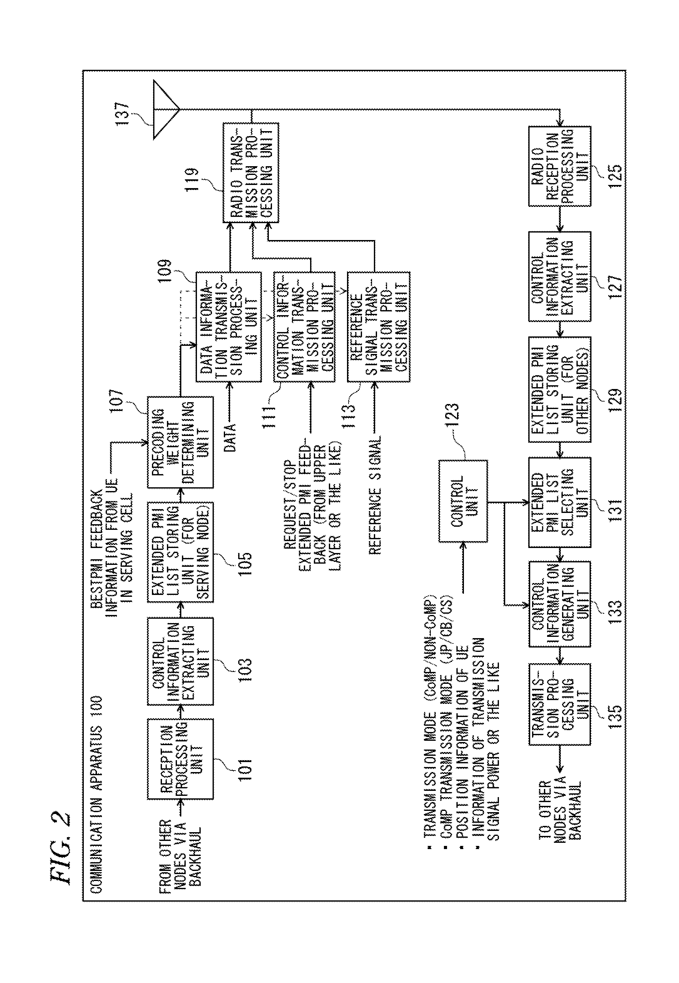
[0119]FIG. 6 shows a block diagram illustrating a configuration of the communication apparatus 100A according to the first modification example.
[0120]The communication apparatus (base station (NodeB)) 100A shown in FIG. 6 includes a reception processing unit 101, a control information extracting unit 103, an extended PMI list storing unit (for a serving node) 105, a precoding weight determining unit 107, a data information transmission processing unit 109, a control information transmission processing unit 111, a reference signal transmission processing unit 113, a scheduler unit 115, a transmission signal power control unit 117, a radio transmission processing unit 119, a unit 121 that generates a transmission power (RNTP) indicator for each frequency resource, a control unit 123, a radio reception processing unit 125, a control information extracting unit 127, an extended PMI list storing unit (for other nodes) 129, an extended PMI list selecting unit 131, a control information generating unit 133, a transmission processing unit 135, and a transmission and reception antenna 137. Hereinafter, in this embodiment, it is assumed that the communication apparatus 100A is located in the NodeB #0 (serving cell).
[0121]The communication apparatus 100A shown in FIG. 6 is different from the communication apparatus 100 shown in FIG. 2 in that the scheduler unit 115, the transmission signal power control unit 117, and the indicator generating unit 121 are provided. Hereinafter, the same reference numbers are given to the same components as the communication apparatus 100 shown in FIG. 2, and a detailed description thereof will not be repeated.
[0122]The scheduler unit 115 determines a frequency resource allocation of a UE in a serving cell and a transmission signal power value for each frequency resource on the basis of QoS (Quality of Service) that is input or CQI (Channel Quality Indicator) that is fed back from a UE. In addition, the scheduler unit 115 outputs this information to the transmission signal power control unit 117.
[0123]The transmission signal power control unit 117 generates a control signal to control an amplifier in the radio transmission processing unit 119 on the basis of the transmission signal power value for each input frequency resource, and outputs the control signal to the radio transmission processing unit 119 and the RNTP indicator generating unit 121.
[0124]The RNTP indicator generating unit 121 generates information (RNTP indicator) about a magnitude of a future (for example, after 1 frame) transmission signal power on the basis of the control signal and a threshold value of the RNTP that are input from the transmission signal power control unit 117, and outputs the generated information to the control unit 123.
[0125]The control unit 123 compares the extended PMI list that is generated for each frequency resource input from the extended PMI list storing unit (for other nodes) 129, and the information of the magnitude of the transmission signal power (density) (information of RNTP indicator) for each frequency resource in the serving cell or the like in correlation with each other. In addition, the control unit 123 selects the extended PMI list of the frequency resource on the basis of the information of the magnitude of the transmission signal power (density) (information of RNTP indicator) for each frequency resource.
[0126]FIG. 7 shows an example of the extended PMI list in the first modification example. In FIG. 7, the information of the magnitude of the (future) transmission signal power for each frequency resource is correlated with the extended PMI (worst PMI) list that is selected by the control unit 123. As shown in FIG. 7, since a UE that is present at a cell edge is to be allocated to physical resource block (PRB) numbers of #0 and #3 in the future (for example, after one frame), the transmission signal power of the frequency resource is set to be high. Therefore, the number of the frequency resource position is output to the extended PMI list selecting unit 131.
[0127]The extended PMI list selecting unit 131 selects the extended PMI list (in the case of extended PMI list shown in FIG. 7, extended PMI lists of PRB number #0 and PRB number #3) of the frequency resource position, which is notified from the control unit 123, and outputs the selected extended PMI list to the control information generating unit 133. As described above, the information of the selected frequency resource position (for example, a bit sequence (bitmap) representing frequency resource position at which the PMI is notified, which is shown in FIG. 5) may be also output to the control information generating unit 133.
[0128]The control information generating unit 133 generates control information by performing a process of converting the extended PMI list (and the cell ID and group cell ID) input from the extended PMI list selecting unit 131 and the notification frequency resource number that is input from the control unit 123 into a binary sequence, or the like, and outputs the generated control information to the transmission processing unit 135.
[0129]After adding a header representing a destination address of a transmission node (cell) or the like with respect to the extended PMI list (and cell ID and group cell ID) and the notification frequency resource number that are input with reference to the information of the cell ID, the transmission processing unit 135 performs a predetermined processing to generate a transmission signal over the backhaul and transmits this signal to other nodes (cells).
[0130]The reception processing unit 101 receives control information related to the extended PMI list (and the cell ID and group cell ID) and the notification frequency resource number that are transmitted from other nodes (cells), performs a predetermined processing such as confirmation of the destination address or the like, and then outputs the control information to the control information extracting unit 103.
[0131]The control information extracting unit 103 extracts the extended PMI list (and the cell ID and group cell ID) and the notification frequency resource number that are included in the control signal and are transmitted from other nodes (cells), and outputs them to the extended PMI list storing unit (for a serving node) 105.
[0132]The extended PMI list storing unit (for a serving node) 105 generates the extended PMI list for each of other cells or for each cell group, and for each frequency resource, and outputs this information to the precoding weight determining unit 107.
[0133]The precoding weight determining unit 107 determines, for example, a precoding weight for each frequency resource that maximizes the cell throughput or a precoding weight for each UE within a serving cell on the basis of the best PMI feedback information for each frequency resource, which is input from the UE of the serving cell, the extended PMI list for each frequency resource of other cells (or for each cell group), which is input from the extended PMI list storing unit (for a serving node) 105. In addition, the determined weight information is output to the data information transmission processing unit 109, the control information transmission processing unit 111, or the reference signal transmission processing unit 113.
[0134]The data information transmission processing unit 109 performs a predetermined processing such as channel encoding and modulation with respect to the input data signal for the UE, and then performs precoding with respect to a transmission data signal on the basis of the weight information input from the precoding weight determining unit 107. Then, the data information transmission processing unit 109 outputs the pre-coded data signal to the radio transmission processing unit 119.
[0135]In addition, the control information transmission processing unit 111 and the reference signal transmission processing unit 113 may perform precoding with respect to a control signal and a reference signal (particularly, DMRS) on the basis of the precoding weight information input from the precoding weight determining unit 107.
[0136]A flow illustrating a control sequence of the transmission system according to the first modification example will be described with reference to FIG. 8. FIG. 8 shows a flowchart illustrating a control sequence of the transmission system according to the first modification example.
[0137]In step ST81, the NodeB #0 (serving cell) transmits an extended PMI (beamforming) request signal toward a UE.
[0138]In steps ST82 and ST83, the UE receives a reference signal of the NodeB #0 that is a serving cell, and a reference signal of the NodeB #1 (non-serving cell) that is another cell.
[0139]In step ST84, the UE feedback-transmits the PMI information to the NodeB #0 as a control signal.
[0140]In step ST85, the NodeB #0 receives the PMI information from other UEs that are connected to the serving cell.
[0141]In step ST86, the NodeB #0 generates and selects the PMI information in response to information of the transmission power (density), (normalized) transmission signal energy (density), or a magnitude (good or bad) of a communication quality for each frequency resource in the serving cell.
[0142]In step ST87, the NodeB #0 notifies the NodeB #1 of the PMI information and information of the selected frequency band position.
[0143]In step ST88, the NodeB #0 notifies other NodeBs of the PMI information and the information of the selected frequency band position.
[0144]As described above, according to the transmission system related to the first modification example, the communication apparatus 100A may autonomously select precoding (beamforming) information in a specific resource, which other nodes need for the ICIC, only with the serving node on the basis of information (for example, an RNTP indicator) about the magnitude of future transmission signal power in the serving cell, such that overhead related to the PMI (beamforming weight (for example, the number of PMI lists information) that is notified over the backhaul may be reduced.
[0145]In addition, in addition to the future transmission power (density) information for each frequency resource in the serving cell, the communication apparatus 100A may correlate information of the (normalized) transmission signal energy (density) or the magnitude (good or bad) of the communication quality (CQI), or the like, and the amount of precoding (beamforming) information (for example, the number of PMI lists) at the frequency resource position with each other. Therefore, the same effect as that obtained by the transmission system related to the above-described first modification example may be obtained.
[0146]In addition, in a case where the communication apparatus 100A notifies other nodes of the future transmission power (density) information, the (normalized) transmission signal energy (density), or the magnitude (good or bad) of the communication quality (CQI) for each frequency resource together with each other, the information of the selected frequency resource position may not be notified. When the above-described correlation rule is shared between coordination nodes, for example, since the frequency resource at which the PMI is notified may be specified from the notified transmission power information for each frequency resource, even when the position information of the selected frequency resource is not notified, the same effect as that obtained by the transmission system related to the first modification example may be obtained.
Example
Second Modification Example
[0147]As the transmission power (density) or (normalized) transmission signal energy (density) for each frequency resource in the serving cell is large (or small), or as the communication quality becomes better (or worse) for each frequency resource in the serving cell, a communication apparatus of a second modification example related to the first embodiment allows the extended PMI list selecting unit 131 to increase (or decrease) the amount of the precoding (beamforming) information (for example, the number of PMI lists) at a corresponding resource.
[0148]Here, an operation of the communication apparatus of the second modification example related to the first embodiment is different from the operation of the communication apparatus 100A in an operation of the extended PMI list selecting unit 131, and therefore, in this modification example, the operation of the extended PMI list selecting unit 131 that performs the different operation will be mainly described.
[0149]The operation of the extended PMI list selecting unit 131 in the transmission system related to the second modification example will be described with reference to FIG. 9. FIG. 9 shows an example of the extended PMI list in the second modification example. In FIG. 9, the transmission power (density) for each frequency resource is also shown in the extended PMI list. In the extended PMI list shown in FIG. 9, the number of extended PMI lists at a frequency resource varies in response to the magnitude of the transmission signal power for each frequency resource.
[0150]As shown in FIG. 9, the extended PMI list selecting unit 131 sets two threshold values (a transmission signal power threshold value 1 and a transmission signal power threshold value 2) to the transmission signal power, and defines the magnitude of the transmission signal power in three regions (“large”, “middle”, and “small”). At this time, (1) when the value of the transmission signal power is in the “small” region, the number of extended PMI lists to be notified is set to 0, (2) when the value of the transmission signal power is in the “middle” region, the number of PMI lists to be notified is set to 1, and (3) when the value of the transmission signal power is in the “large” region, the number of extended PMI lists to be notified is set to 2,
[0151]In addition, the extended PMI list selecting unit 131 selects the extended PMI for each frequency resource, that is, for PRB numbers of #0 to #7 on the basis of the number of extended PMI lists depending on the magnitude of the transmission signal power.
[0152]For example, as shown in FIG. 9, at PRB #1, since the value of the transmission signal power is in the “large” region, the number of extended PMI lists to be notified becomes 2. Therefore, at PRB #1, two extended PMIs of extended PMI #1 and extended PMI #0 are selected. In addition, at PRB #4, since the value of the transmission signal power is in the “small” region, the number of extended PMI lists to be notified becomes 0. Therefore, at PRB #4, the extended PMI is not selected in the extended PMI list shown in FIG. 9.
[0153]As described above, in the transmission system related to the second modification example, the larger (or smaller) the transmission signal power for each frequency resource, the further the extended PMI list selecting unit 131 increases (or decreases) the amount of the precoding (beamforming) information (for example, the number of PMI lists) at this resource.
[0154]Therefore, in regard to the transmission system related to the second modification example, the communication apparatus of the second modification example related to the first embodiment increases coordination CB/JP information only in a specific frequency resource in which large interference may be applied to other cells with high probability when seen from the serving node (large interference from other cells when seen from other nodes), such that the ICI reduction effect due to the coordination ICIC among a plurality of nodes may be further improved.
[0155]In addition, in regard to the transmission system related to the second modification example, the communication apparatus of the second modification example related to the first embodiment may perform correlation with respect to the amount of the beamforming information in a corresponding band on the basis of the transmission signal power density and the (normalized) transmission signal energy (density) in addition to the transmission signal power for each frequency resource. For example, the larger (or smaller) the transmission signal power density, the (normalized) transmission signal energy (density), the further the amount of the precoding (beamforming) information (for example, the number of PMI lists) at a corresponding resource may be increased (or decreased). Therefore, the same effect as described above may be obtained.
[0156]In addition, in regard to the transmission system related to the second modification example, the communication apparatus of the second modification example related to the first embodiment may correlate communication quality (CQI (Channel Quality)) information (SIR (Signal-to-Interference Ratio), SINR (Signal-to-Interference plus Noise Ratio), or the like) that is fed back from a UE, and the amount of the beamforming information at a corresponding band with each other. In addition, the communication apparatus may correlate measurement information (RSRP, RSRQ, RSSI, or the like) that is fed back from a UE, and the amount of the beamforming information at a corresponding band with each other. For example, the larger (or smaller) the communication quality (CQI (Channel Quality)), RSRP, RSRQ, or the like), the further the amount of the precoding (beamforming) information (for example, the number of PMI lists) may be increased (or decreased) at a corresponding resource. Therefore, even when a UE, which needs a high-speed rate (needs high CQI (SINR)), other than a UE that is present at a cell edge is allocated to the frequency resource, inter-cell interference with respect to the UE may be reduced.
Login to view more PUM


Description & Claims & Application Information
We can also present the details of the Description, Claims and Application information to help users get a comprehensive understanding of the technical details of the patent, such as background art, summary of invention, brief description of drawings, description of embodiments, and other original content. On the other hand, users can also determine the specific scope of protection of the technology through the list of claims; as well as understand the changes in the life cycle of the technology with the presentation of the patent timeline. Login to view more.
Login to view more Similar technology patents
Monitor Chaining and Docking Mechanism
ActiveUS20120062800A1Reduce overheadColor signal processing circuitsCathode-ray tube indicatorsVIT signalsPhysical interface
Owner:SMSC HLDG
User terminal safety communication method in platform of Internet of Things
InactiveCN102780698ASafe and reliableReduce overheadTransmissionData transmissionSecure communication
Owner:NANJING UNIV OF POSTS & TELECOMM
Method for transition between distributed transmission and localized transmission
ActiveUS20090130985A1Reduce overheadModulated-carrier systemsTransmission monitoringTransfer modeFrequency domain
Owner:SAMSUNG ELECTRONICS CO LTD +1
Automatic operation maintenance monitoring system
InactiveCN106487574AReduce overheadEasy for statistical analysisData switching networksGoal systemData monitoring
Owner:NAT COMP NETWORK & INFORMATION SECURITY MANAGEMENT CENT
Preamble design method for reducing overhead during handover in hierarchical cellular system
Owner:SAMSUNG ELECTRONICS CO LTD +1
Classification and recommendation of technical efficacy words
- Reduce overhead
- Reduce effect
Low overhead fault tolerance through hybrid checkpointing and replay
ActiveUS20100107158A1Reduce overheadSoftware simulation/interpretation/emulationSpecial data processing applicationsVirtualizationLow overhead
Owner:VMWARE INC
Method and system for providing secure, centralized access to remote elements
ActiveUS7640581B1Reduce overheadReduce eliminateMultiple digital computer combinationsProgram controlNetwork elementSecurity Measure
Owner:CENTURYLINK INTPROP
Downhole data transmission system
InactiveUS20040104797A1Reduce overheadElectric signal transmission systemsSurveyTransmission systemData transmission systems
Owner:INTELLISERV
Row-diagonal parity technique for enabling efficient recovery from double failures in a storage array
ActiveUS6993701B2Reduce overheadInput/output to record carriersStatic storageTheoretical computer scienceDouble fault
Owner:NETWORK APPLIANCE INC
Systems and methods for hydrocarbon recovery
InactiveUS6173775B1Difficult to maintainReduce effectInsulationFluid removalHydrogen compoundsInjector
Owner:ELIAS RAMON +2
Clip applier cartridge with internal ratchet
InactiveUS20050256529A1Reduce effectImproves seatSuture equipmentsSurgical staplesEngineeringRisk stroke
Owner:YAWATA HARUYASU +2
Space-time and space-frequency hopping for capacity enhancement of mobile data systems
ActiveUS7016649B1Increase capacityReduce effectPower managementSubstation equipmentBeam hoppingSelf adaptive
Owner:F POSZAT HU
System, method and apparatus for treating liquids with wave energy from plasma
ActiveUS20070253874A1High processing rateReduce effectReversed direction vortexWater/sewage treatment by irradiationPlasma torchEngineering
Owner:FORET PLASMA LABS