Systems and methods for landmark correction in magnetic resonance imaging

a landmark correction and magnetic resonance imaging technology, applied in the field of landmark correction in magnetic resonance imaging, can solve the problems of incorrect patient positioning, inaccurate patient positioning, and the anatomy of the patient used for automated scan plane prescriptions

Active Publication Date: 2013-10-24
GENERAL ELECTRIC CO
View PDF7 Cites 36 Cited by
  • Summary
  • Abstract
  • Description
  • Claims
  • Application Information

AI Technical Summary

Problems solved by technology

The landmark procedure, like any human process, is subject to error.
While a landmark error is undesirable, it is also problematic in the context of a MRI examination with automated scan plane prescription.
If the patient is improperly landmarked by the operator, images used for the automated scan plane prescription may not contain the patient anatomy needed for proper computation of scan planes.
Consistency in manual landmarking, however, may be difficult for complex anatomies like the heart or joints, sometimes leading to incorrect patient positioning.
In particular, an error in judging the relative position of the coil by the operator may

Method used


Image

  • Systems and methods for landmark correction in magnetic resonance imaging
  • Systems and methods for landmark correction in magnetic resonance imaging
  • Systems and methods for landmark correction in magnetic resonance imaging

Examples


Embodiment Construction

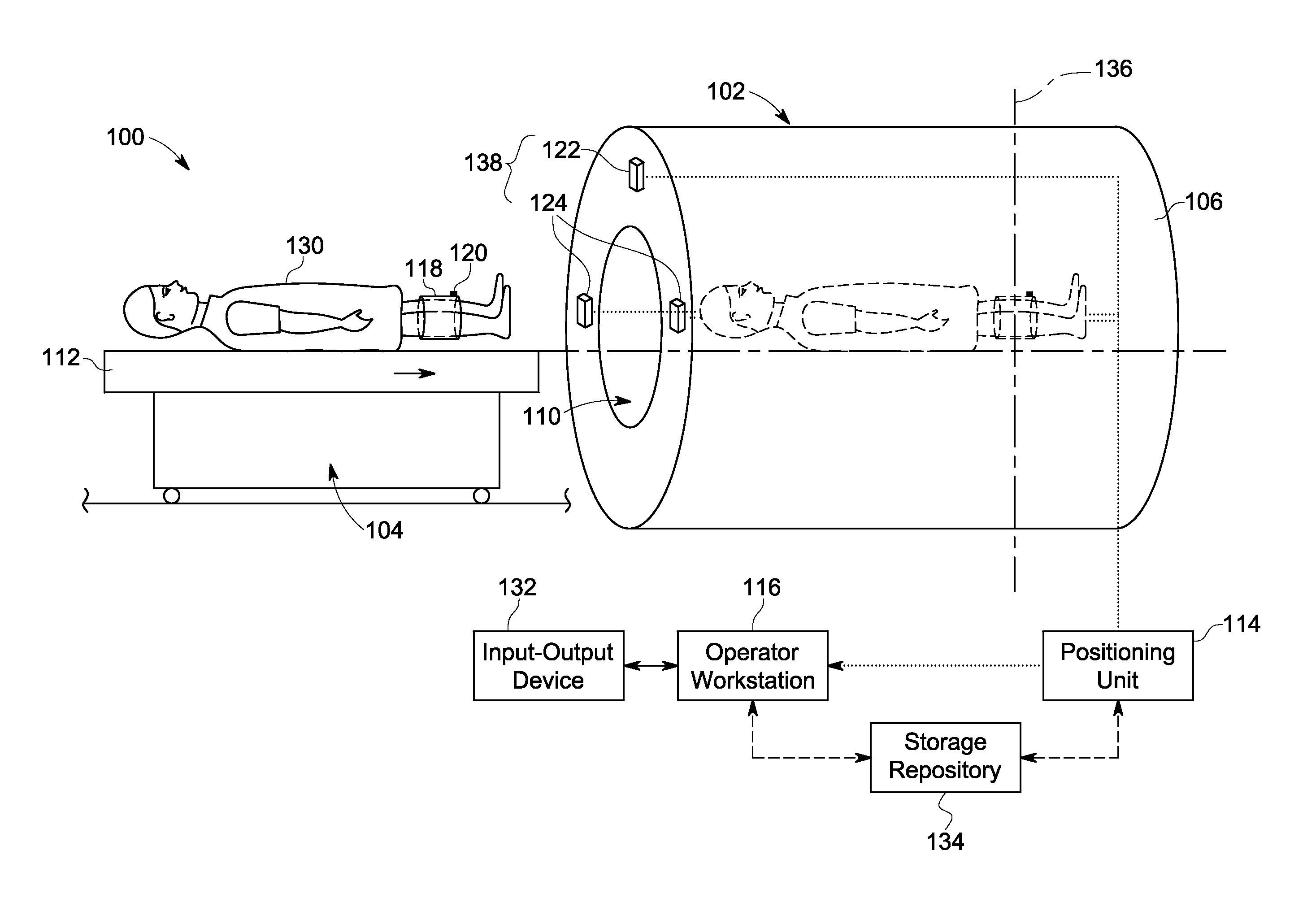
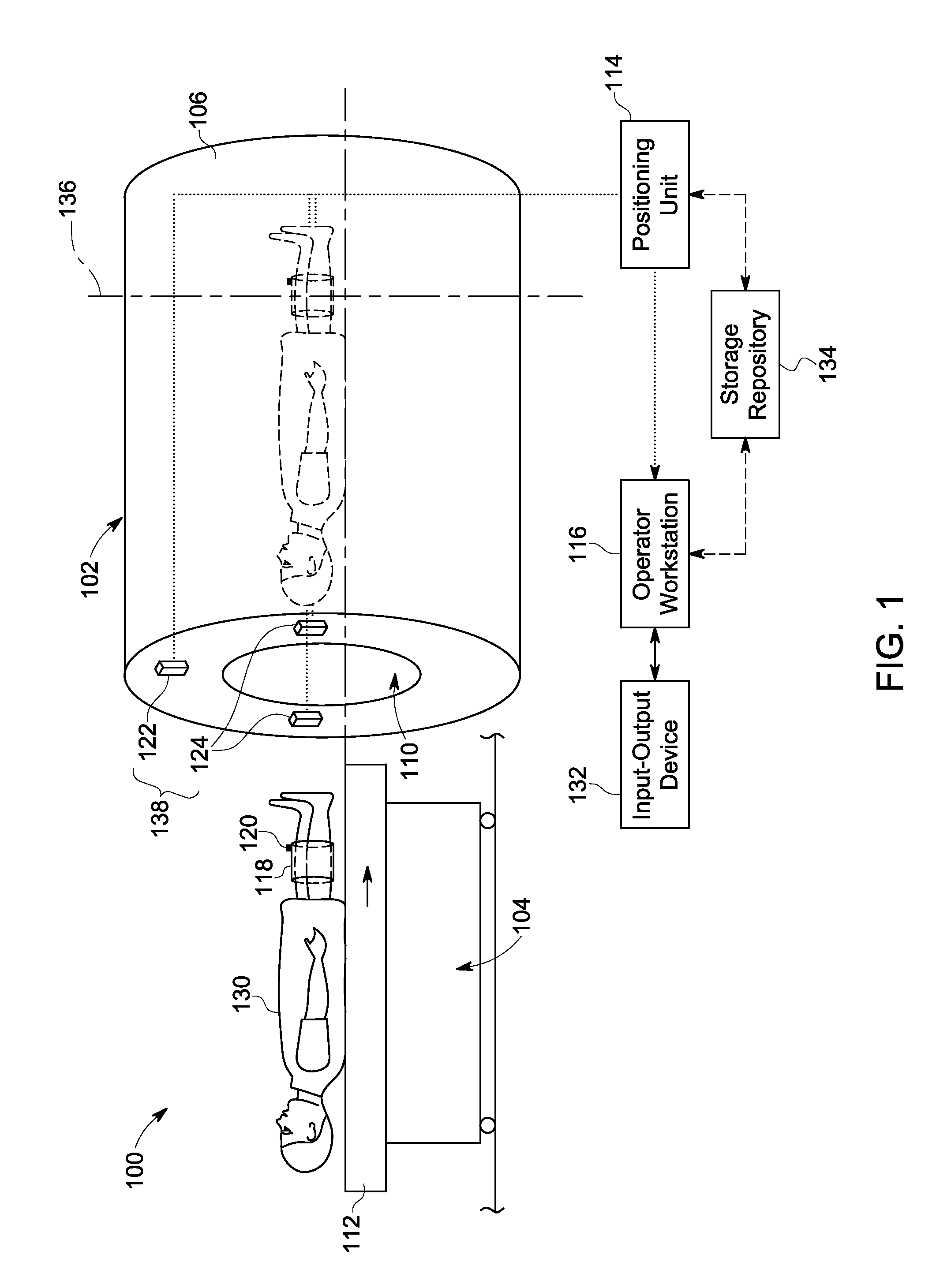
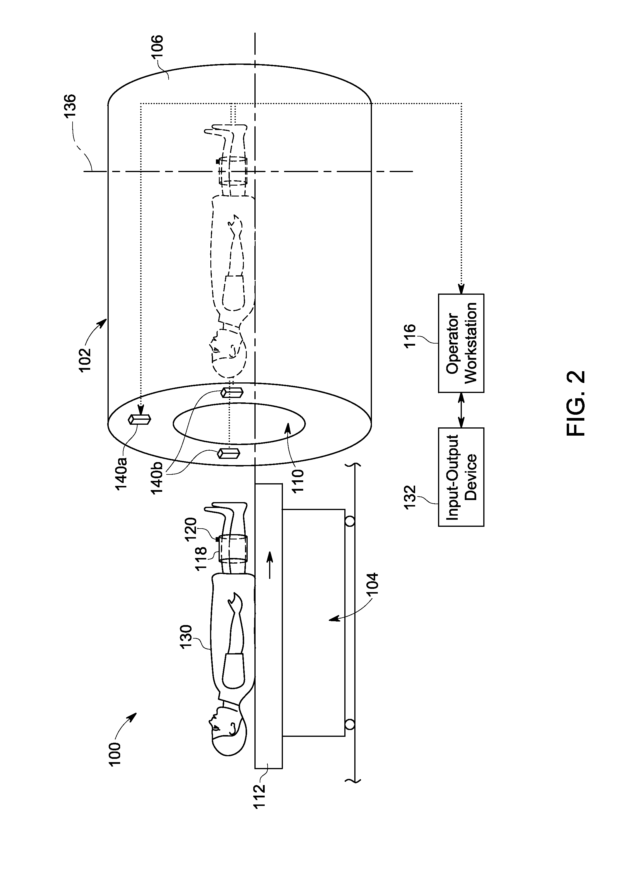
[0020]The following detailed description of certain embodiments will be better understood when read in conjunction with the appended drawings. To the extent that the figures illustrate diagrams of the functional blocks of various embodiments, the functional blocks are not necessarily indicative of the division between hardware. Thus, for example, one or more of the functional blocks may be implemented in a single piece of hardware or multiple pieces of hardware. It should be understood that the various embodiments are not limited to the arrangements and instrumentality shown in the drawings. Additionally, the system blocks in the various figures or the steps of the methods may be rearranged or reconfigured.

[0021]As used herein, an element or step recited in the singular and proceeded with the word “a” or “an” should be understood as not excluding plural of said elements or steps, unless such exclusion is explicitly stated. Furthermore, references to “one embodiment” are not intended...


PUM


Abstract

Systems and methods for landmark correction in Magnetic Resonance Imaging (MRI) are provided. One method includes acquiring at least one calibration image or at least one localizer image of an object, identifying in the calibration or localizer images a region of the object as a reference point, wherein the reference point defines a landmark position. The method further includes determining an offset between an initial landmark position and the identified landmark position. The method also includes using the determined offset for MRI.

Description

BACKGROUND[0001]Diagnostic imaging procedures often use specific scan configurations that allow acquisition and reconstruction of imaging data from a desired region of interest (ROI) of a subject, such as a patient. Magnetic Resonance Imaging (MRI), for example, includes a plurality of scan configurations that specify parameters related to patient position, positioning of radio-frequency coils (RF) and landmarking an ROI of the patient for specific imaging protocols. In particular, landmarking registers a patient with a scanner coordinate system to allow an imaging volume to be moved to a homogeneous, imaging portion, for example, an iso-center of a magnet of the MRI system for desired imaging.[0002]The landmarking process is many times a manual process in which a MRI system operator defines the center of an imaging region through mechanical, optical, or other suitable means. For example, the system operator may position the patient on an examination table, position a magnet resonan...

Claims


Application Information

Patent Timeline
IPC IPC(8): G06K9/00
CPCA61B5/055G01R33/543
Inventor DARROW, ROBERT DAVIDFOO, THOMASFUNG, MAGGIEVAIDYA, VIVEK PRABHAKARTAO, XIAODONG
Owner GENERAL ELECTRIC CO
Why Eureka
Try Eureka