
Method and system for implementing a redo repeater

a repeater and redo technology, applied in the field of methods and systems for implementing redo repeaters, can solve the problems of reducing the efficiency of redo record implementation, and reducing the cost of performance costs, so as to achieve negligible performance impact, low cost, and high performance

Active Publication Date: 2013-10-24
ORACLE INT CORP
View PDF14 Cites 3 Cited by
  • Summary
  • Abstract
  • Description
  • Claims
  • Application Information

AI Technical Summary

Benefits of technology

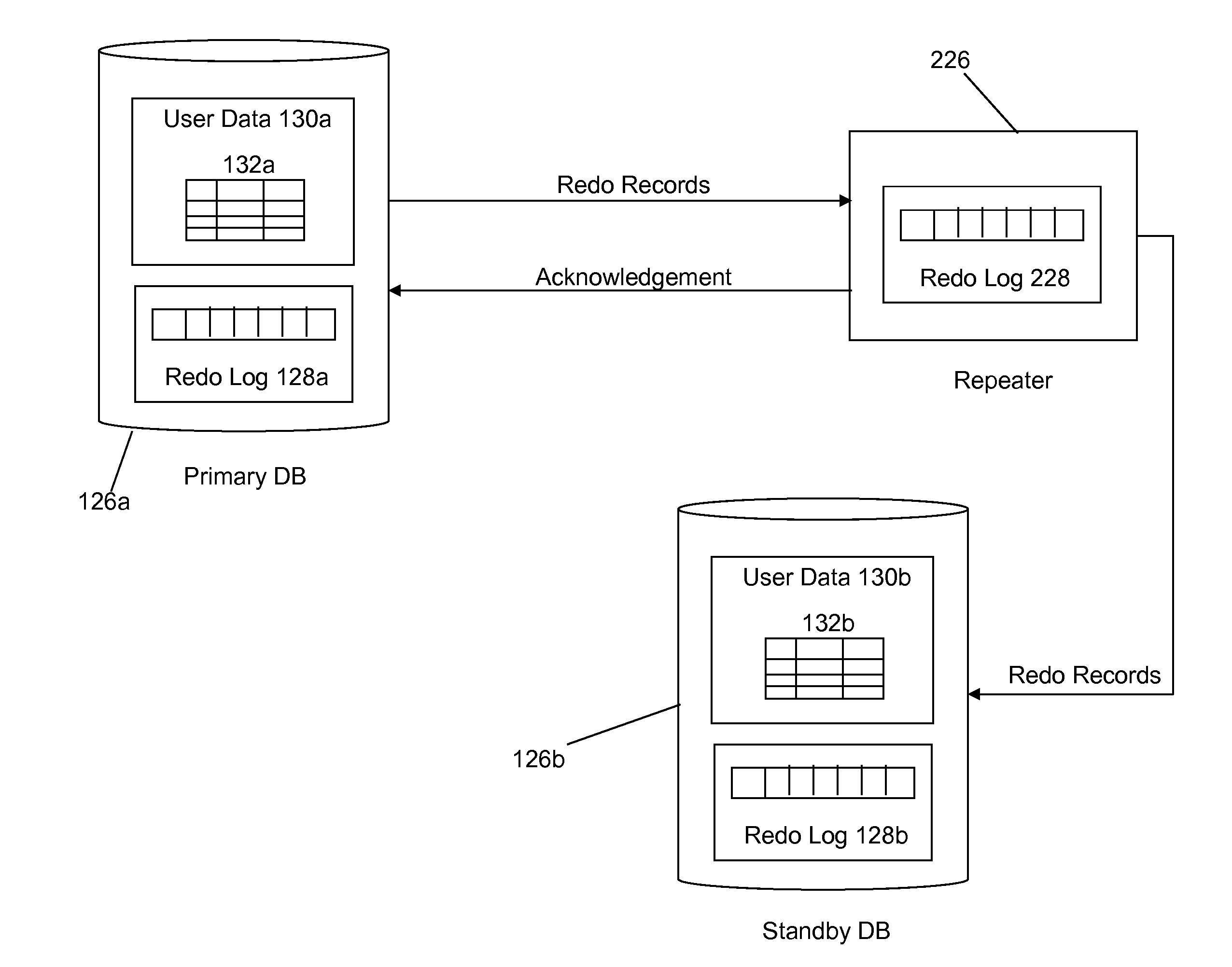
The invention introduces a Repeater that can handle the workload of multiple standby databases. This means that the Repeater can offload this type of workload from the primary database, reducing the burden on it.

Problems solved by technology

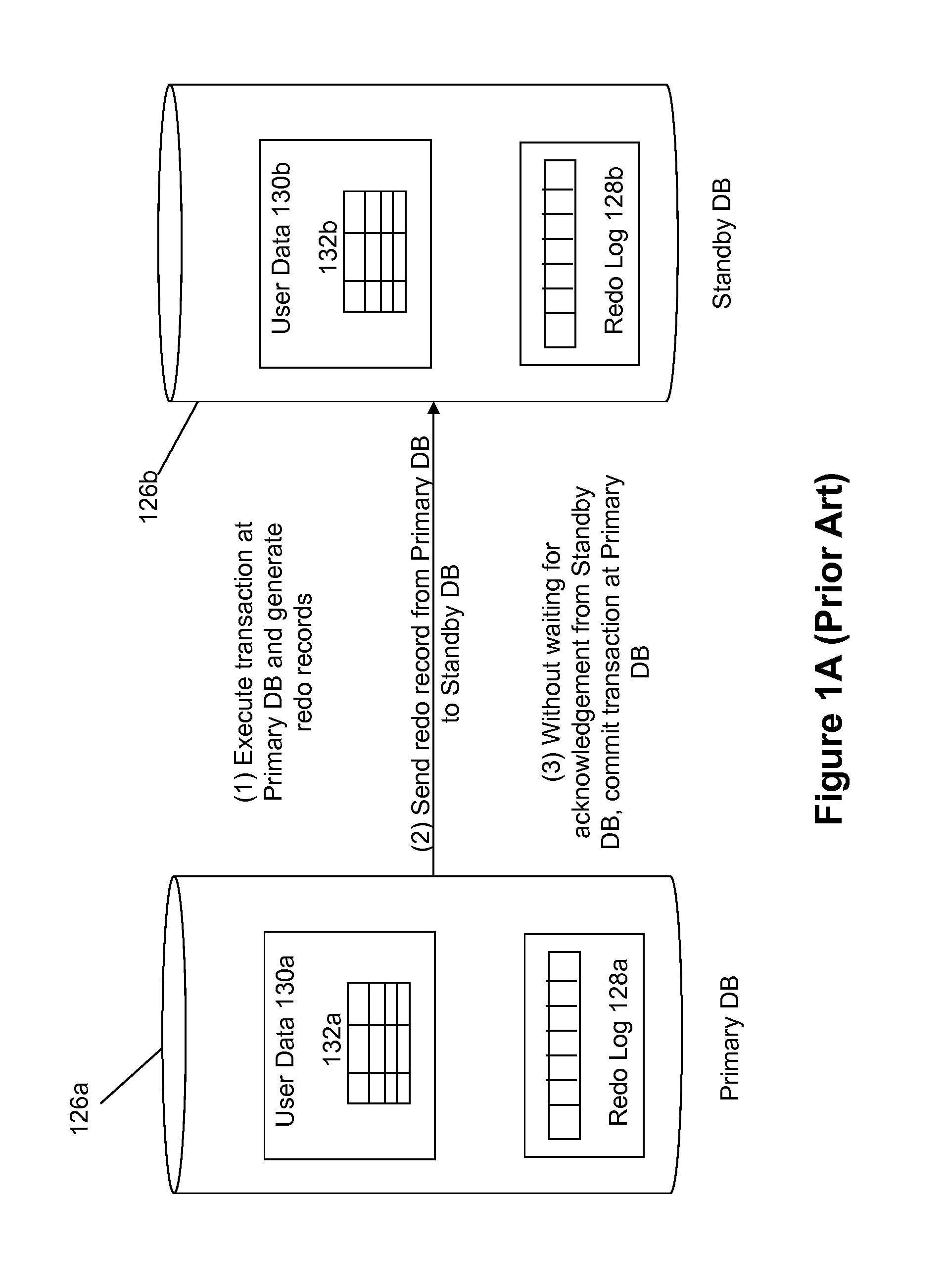
However, this configuration runs the risk of possible data loss since there is no confirmation that the redo records have actually been received at the standby database, and therefore in the event of a failure it is possible the changes made by the transaction associated with the redo records can be lost.
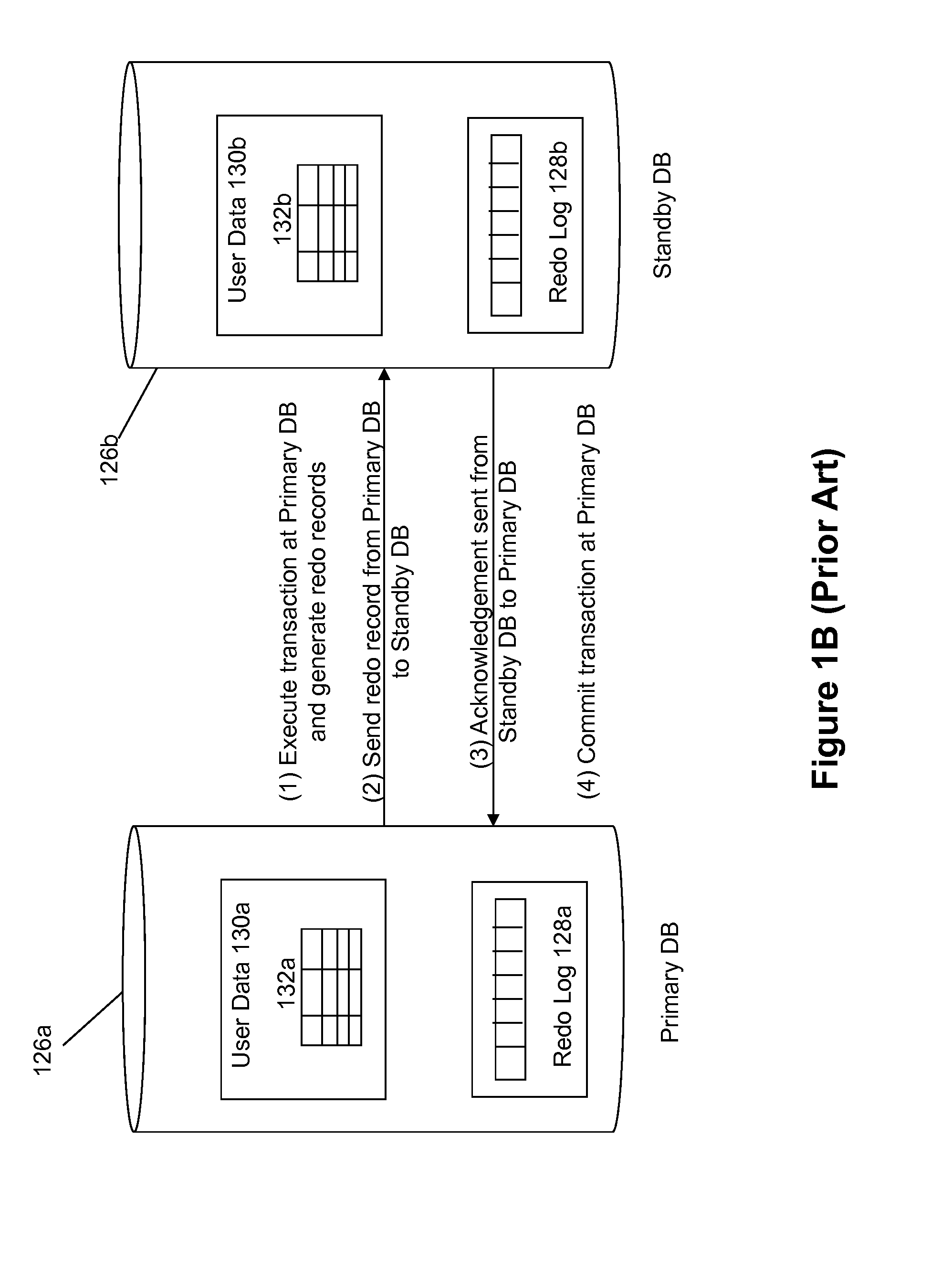
The no data loss approach provides greater assurance of data security as compared to the high performance approach, but at the expense of performance costs.
Since standby databases are normally located geographically distant from the primary database (e.g., to reduce the chance of a single point of failure affecting both the primary and the standby), the network latency is typically quite significant.
Therefore, the no data loss configurations protect against data loss from any single source of failure at the expense of possibly degrading the performance of the primary database.
The degree of performance degradation is directly tied to the network latency between the primary and standby databases.
The greater the geographical distance between the primary and standby database, the greater the network latency between them.
In contrast, the high performance configuration minimizes commit delays, but runs the risk of possible data loss since there is no confirmation that the redo records have actually been received at the standby database.

Method used


Image

  • Method and system for implementing a redo repeater
  • Method and system for implementing a redo repeater
  • Method and system for implementing a redo repeater

Examples


Embodiment Construction

[0028]Various embodiments are described hereinafter with reference to the figures. It should be noted that the figures are not drawn to scale and that the elements of similar structures or functions are represented by like reference numerals throughout the figures. It should be noted that the figures are only intended to facilitate the description of the embodiments. They are not intended as an exhaustive description of the invention or as a limitation on the scope of the invention. In addition, an illustrative embodiment need not have all the aspects or advantages shown. An aspect or an advantage described in conjunction with a particular embodiment is not necessarily limited to that embodiment and can be practiced in any other embodiments even if not so illustrated. Also, reference throughout this specification to “some embodiments” or “other embodiments” means that a particular feature, structure, material, or characteristic described in connection with the embodiments is include...


PUM


Abstract

Disclosed are methods and apparatuses to provide a redo repeater that allows for no data loss protection without the performance impact to the primary database even when a significant geographical distance separates the primary and standby databases. The Repeater is a lightweight entity that receives redo from the primary database with the purpose of redistributing that redo throughout the primary / standby system configuration. The Repeater able to extend no data loss protection and switchover functionality to terminal standby databases even though the primary database does not need to have a direct connection with those destinations.

Description

CROSS-REFERENCE TO RELATED APPLICATIONS[0001]This Application is related to co-pending U.S. patent application Ser. No. ______, entitled “METHOD AND SYSTEM FOR IMPLEMENTING A CONDITIONAL REDO REPEATER” (Attorney Docket Number ORA120318-US-NP2), filed on even date herewith, which is hereby incorporated by reference in its entirety.BACKGROUND AND SUMMARY[0002]Many enterprises use computer databases to store, organize, and analyze some of their most important information. For example, a business may employ a database to hold its sales and ordering information so that analysts can predict trends in product sales or perform other kinds of data mining for long-range planning Because database systems are responsible for managing information vital to the organization's operation, it is important for mission-critical database systems to implement mechanisms for recovery following a database system failure.[0003]One approach to implement disaster recovery by deploying a “standby” database sys...

Claims


Application Information

Patent Timeline
Patent Type & Authority Applications(United States)
IPC IPC(8): G06F17/30
CPCG06F16/275
Inventor MCGEE, STEVENLUO, JIANGBINGARIN, BENEDICTOGIRKAR, MAHESHHARVEY, MICHAELKARKHANIS, NITINLEE, STEVELOAIZA, JUANMCGUIRK, ROBERTYANG, HONGJIE
Owner ORACLE INT CORP
Learn More