
Mobile test system and methods for in situ characterization of stress and deflection dependent stiffness and bearing capacity of soils and geo-materials

a mobile test system and in situ characterization technology, applied in the direction of material strength using tensile/compressive forces, instruments, foundation engineering, etc., can solve the problems of inability to characterize static or cyclic stress and deflection dependent stiffness and bearing capacity, inability to provide measurements, and inability to control the construction process to achieve directly measured values

Active Publication Date: 2013-10-31
INGIOS GEOTECHNICS INC
View PDF1 Cites 9 Cited by
  • Summary
  • Abstract
  • Description
  • Claims
  • Application Information

AI Technical Summary

Benefits of technology

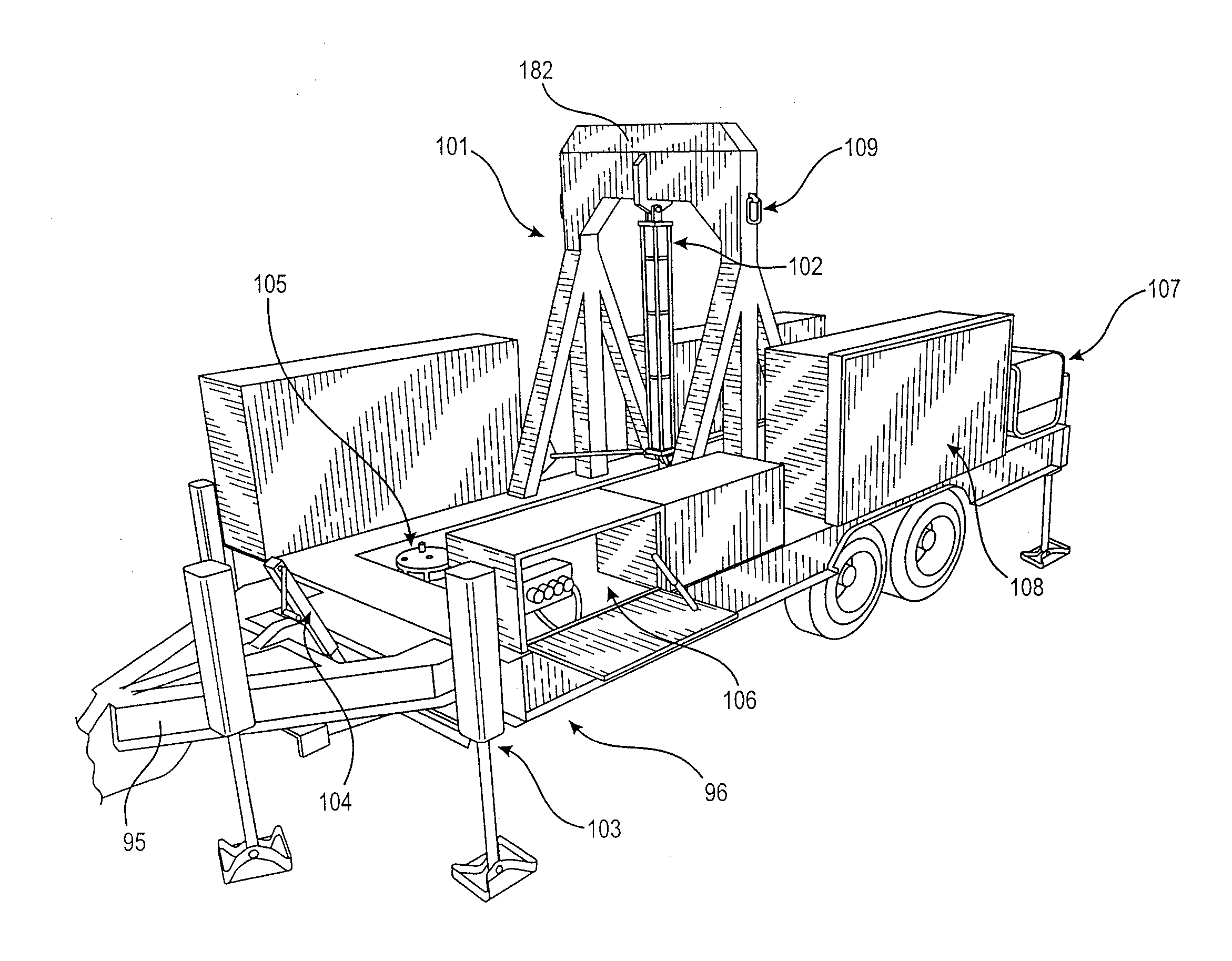
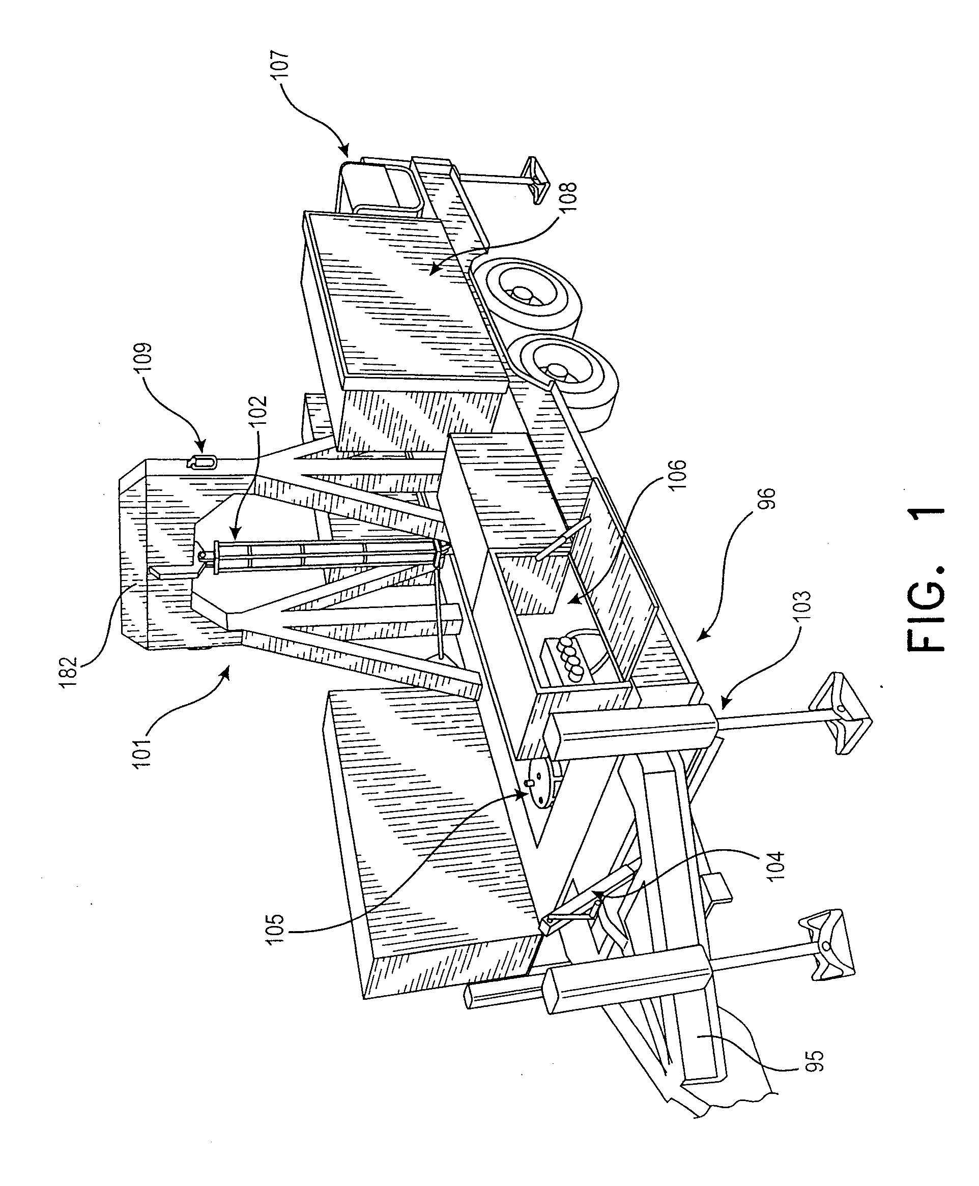
The invention is a mobile test system that can level and balance a trailer to maximize the reaction load on the ground. It achieves this using outrigger hydraulic jacks and a moveable counterbalance weight system. The system also has integrated level sensors to provide feedback to a hydraulic control system for automated trailer leveling. The invention also aims to improve measurement techniques for determining the stiffness and bearing capacity of different materials and conditions associated with soil and geo-materials.

Problems solved by technology

Although used for design, during construction these parameter values are not regularly measured as part of field quality control and quality assurance inspection processes due to lack of suitable field equipment and methods.
Thus, construction processes are not field controlled to achieve the directly measured values provided in design documents.
However, the aforementioned methods do not characterize the static or cyclic stress and deflection dependent stiffness and bearing capacity.
However, a disadvantage of these conventional test methods is that they (i) do not provide measurements under static conditions, (ii) only use a flat plate or a ring for transmitting the load to the ground, (iii) are only suitable for selected material conditions due to limits in the sensor systems, (iv) do not provide for confining stress control around the loading area, and (v) do not allow for strain or deflection controlled testing.

Method used


Image

  • Mobile test system and methods for in situ characterization of stress and deflection dependent stiffness and bearing capacity of soils and geo-materials
  • Mobile test system and methods for in situ characterization of stress and deflection dependent stiffness and bearing capacity of soils and geo-materials
  • Mobile test system and methods for in situ characterization of stress and deflection dependent stiffness and bearing capacity of soils and geo-materials

Examples


example i

[0091]Bearing plate tests were performed using the mobile test system 101 in accordance with the present invention at a test site in Iowa on a control test section of a nominal six inches of a crushed limestone aggregate base overlying a lean clay subgrade. The tests were conducted using a 300 mm diameter flat bearing plate without a confinement plate. The bearing plate tests were conducted both on the control section, and on a similar section of ground reinforced with a Tensar® TX160 geogrid. The geogrid reinforcement is commercially available from Tensar International Corporation of Alpharetta, Ga. The test methods used and the methods of their use were consistent with the disclosure provided herein. The testing was designed to compare the load versus deflection characteristics of the control section with that of the geogrid section in accordance with the present invention to determine the ground stiffness and bearing capacity thereof.

[0092]The results presented in FIG. 12 demonst...

example ii

[0094]In this test, bearing plate tests were performed using a 300 mm diameter curved plate (75 mm versine) as shown in FIGS. 4A and 6. The tests were performed using the mobile test system 101 in accordance with the present invention at a test site in Iowa on a control test section of a nominal six inches of a crushed limestone aggregate base overlying a lean clay subgrade. Bearing plate tests were conducted on the control section and on a similar section having the Tensar® TX160 geogrid reinforcement.

[0095]Results from the test are presented in FIGS. 13 (a) and (b). For each of the tests, the curved bearing plate was seated into the ground to generate a vertical indention equal to about 20 mm. The load versus deflection results (FIG. 13(a)) demonstrate a near linear response during the initial load cycle for the control section up to about 17 kN, whereas for the geogrid reinforced section a near linear response is observed up to about 29 kN. The stiffer response of the geogrid rei...

example iii

[0097]In this example, two bearing plate tests were performed using the 300 mm diameter curved bearing plate (38 mm versine). Using the mobile test system 101 in accordance with the present invention, the tests were performed both with and without the confining plate, which provides controlled and uniform contact with the ground around the bearing plate. In this example, the internal diameter of the confining plate was 13 inches (330 mm) and the external diameter was 36 inches (915 mm). A 0.5 inch thick low durometer rubber pad was used to provide uniform stress transfer from the bottom of the confining plate to the ground.

[0098]FIG. 14 shows the deflection versus plate contact stress results for tests performed on a controlled test section with a nominal 12 inches of crushed limestone over a soft lean clay subgrade. As shown in FIG. 14, the test compared the effect on deflection of applying a confining stress of a nominal 5.7 pounds per square inch (as designated by the legend “——...


PUM

PropertyMeasurementUnit
widthaaaaaaaaaa
weightaaaaaaaaaa
diameteraaaaaaaaaa

Abstract

An integrated mobile test system and methods for characterizing in situ stress or strain / deflection—dependent stiffness and bearing capacity enables the testing of engineering properties of natural, compacted, stabilized, and reinforced soils and geo-materials. The mobile test system and associated methods (1) prepare the ground for testing and (2) apply static or cyclic loading to one or more bearing plates of various geometries positioned at the ground surface or below the ground surface to determine both stress and deflection dependent stiffness relationships and the bearing capacity of the soil or geo-material. Optionally, the mobile test system and associated methods (3) apply ground confining stress conditions independent of the bearing plate loading.

Description

CROSS-REFERENCE TO RELATED APPLICATION[0001]This application claims the benefit of priority to U.S. Provisional Application for Patent No. 61 / 621,059 filed Apr. 6, 2012.BACKGROUND OF THE INVENTION[0002]1. Field of Invention[0003]The present invention relates to an apparatus and associated methods for the in situ testing of engineering properties of soils and geo-materials. More specifically, the present invention relates to a mobile test system and associated test methods that determine in situ the stiffness and bearing capacity of soils and geo-materials.[0004]2. Description of the Prior Art[0005]The construction of civil infrastructure such as pavements, embankments, railway beds, airfield, walls, and industrial and commercial buildings typically requires a determination of soil engineering properties for construction verification and design purposes. These properties include the static or cyclic stress-dependent stiffness and bearing capacity of the soil. Although used for design...

Claims


Application Information

Patent Timeline
Patent Type & Authority Applications(United States)
IPC IPC(8): G01N3/10
CPCG01N3/10E02D1/04G01N3/40
Inventor WHITE, DAVID JOSHUASTEFFES, ROBERT FRANKCACKLER, ELLS THOMAS
Owner INGIOS GEOTECHNICS INC
Learn More