Photovoltaic device, photovoltaic system, and vehicle including photovoltaic device

a photovoltaic device and photovoltaic system technology, applied in the direction of pv power plants, battery/cell propulsion, light to electrical conversion, etc., can solve the problems of power loss, reduction of output, and inability to bypass diodes, so as to prevent the adverse effect of variation in the amount of light irradiation and efficient power generation

Inactive Publication Date: 2013-10-31
SHARP KK
View PDF4 Cites 9 Cited by
  • Summary
  • Abstract
  • Description
  • Claims
  • Application Information

AI Technical Summary

Benefits of technology

[0056]According to the configuration, the vehicle in accordance with the present invention prevents the adverse effect of variation in light irradiation (sunlight) on the photovoltaic device. Even if there occurs variation in the amount of light irradiation on the photovoltaic device, the vehicle restrains an imbalance between the irradiated area and the area taken up by the operating unitary power generation sections (cluster power generation sections, photovoltaic device) and thus realizes efficient power generation. In addition, the vehicle supplies generated electric power to a vehicle power supply while restraining the adverse effect of variation in the amount of light irradiation.
[0057]A photovoltaic device in accordance with the present invention prevents the adverse effect of variation in light irradiation (sunlight) which may only occur at a specific series stage (e.g., a local reduction in light irradiation on the unitary power generation sections caused by a shadow). Even if there occurs variation in the amount of light irradiation, the photovoltaic device restrains an imbalance between the irradiated area and the area taken up by the operating unitary power generation sections and thu

Problems solved by technology

Although it is conceivable to use bypass diodes as a countermeasure for random variation in the amount of li

Method used


Image

  • Photovoltaic device, photovoltaic system, and vehicle including photovoltaic device
  • Photovoltaic device, photovoltaic system, and vehicle including photovoltaic device
  • Photovoltaic device, photovoltaic system, and vehicle including photovoltaic device

Examples


embodiment 1

[0119]A photovoltaic device 1 in accordance with the present embodiment will be described in reference to FIGS. 1A to 1F.

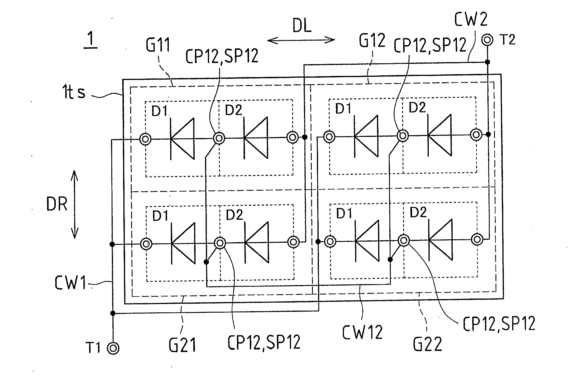
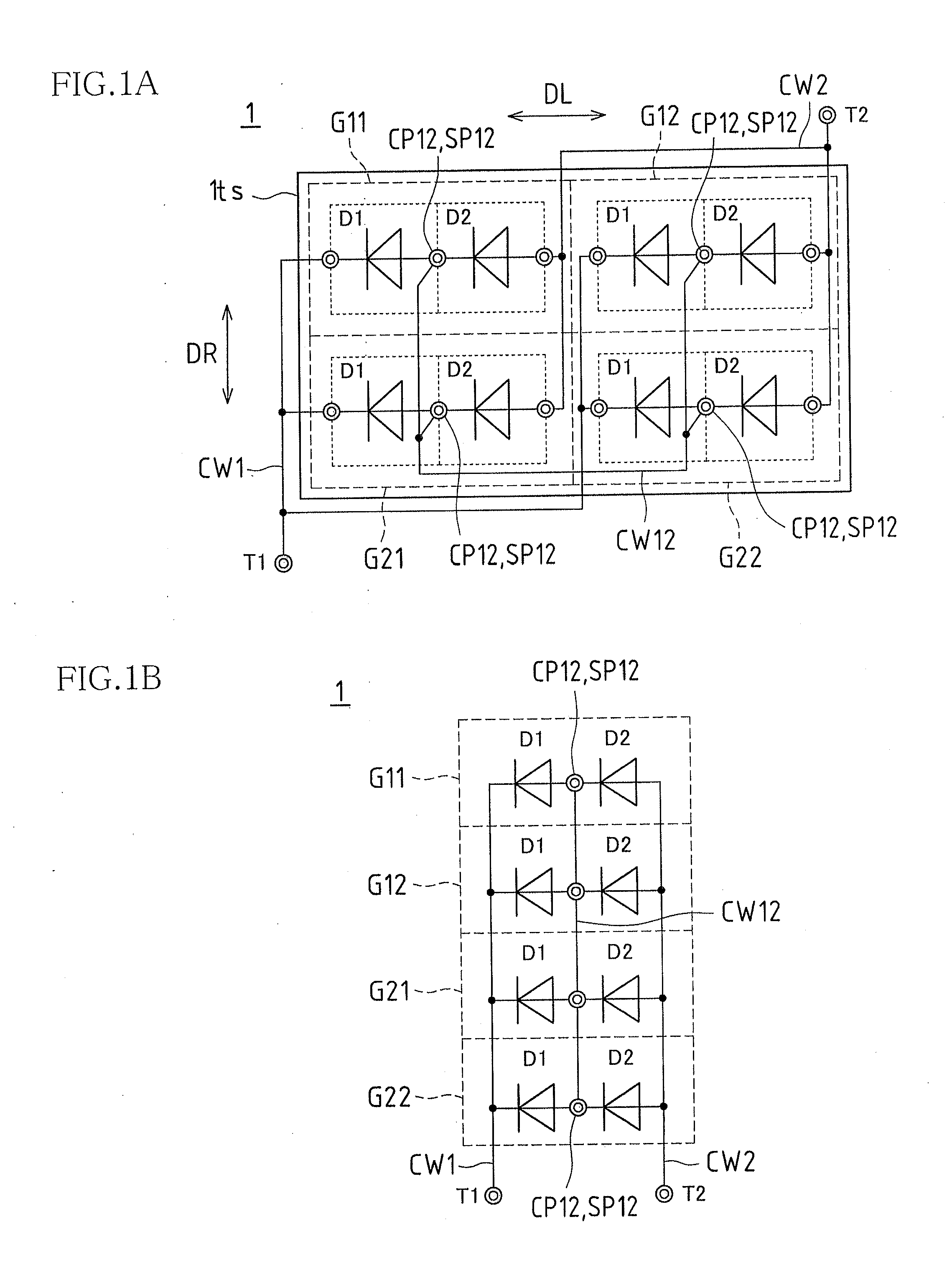
[0120]FIG. 1A is a plan view schematically illustrating the arrangement and connections of unitary power generation sections in a photovoltaic device 1 according to embodiment 1 of the present invention.

[0121]FIG. 1B is an equivalent circuit diagram illustrating, as an equivalent circuit, the connections of the unitary power generation sections in the photovoltaic device 1 shown in FIG. 1A.

[0122]The photovoltaic device 1 in accordance with the present embodiment includes unitary power generation sections D1 and D2 (hereinafter, may be simply referred to as “unitary power generation sections D” when it is not necessary to distinguish between them individually) which convert light to electricity for power generation. The unitary power generation sections D are represented by diode symbols to indicate directionality.

[0123]Each unitary power generation section D is ei...

embodiment 2

[0197]A photovoltaic device 1 in accordance with the present embodiment will be described in reference to FIGS. 2A and 2B. The photovoltaic device 1 in accordance with the present embodiment has a basic configuration similar to that of the photovoltaic device 1 in accordance with embodiment 1 (see FIGS. 1A and 1B). Hence, the same reference numerals will be used where appropriate, and the description will focus on major technical differences.

[0198]FIG. 2A is a plan view schematically illustrating the arrangement and connections of unitary power generation sections in the photovoltaic device 1 in accordance with embodiment 2 of the present invention. Note that the connection wiring CW linking the specific connection points SP (connection points CP) may be omitted in the drawings for clarity throughout the rest of the description.

[0199]FIG. 2B is an equivalent circuit diagram illustrating, as an equivalent circuit, the connections of the unitary power generation sections in the photov...

embodiment 3

[0236]A photovoltaic device 1 in accordance with the present embodiment will be described in reference to FIGS. 3A and 3B. The photovoltaic device 1 in accordance with the present embodiment has a basic configuration similar to that of the photovoltaic devices 1 in accordance with embodiment 1 (see FIGS. 1A and 1B) and embodiment 2 (see FIGS. 2A and 2B). Hence, the same reference numerals will be used where appropriate, and the description will focus on major technical differences.

[0237]FIG. 3A is a plan view schematically illustrating the arrangement and connections of unitary power generation sections in the photovoltaic device 1 in accordance with embodiment 3 of the present invention.

[0238]FIG. 3B is an equivalent circuit diagram illustrating, as an equivalent circuit, the connections of the unitary power generation sections in the photovoltaic device 1 shown in FIG. 3A.

[0239]The photovoltaic device 1 in accordance with the present embodiment includes unitary power generation se...


PUM


Abstract

Disclosed is a photovoltaic device 1 including a plurality of cluster power generation sections G (G11, G12, G21, and G22). Each cluster power generation section G includes unitary power generation sections D (D1, D2) connected in series via connection points CP12. The cluster power generation sections G each have at least a predetermined one of the connection points CP12 designated as a specific connection point SP12. The specific connection points SP12 are connected together to link the cluster power generation sections G.

Description

REFERENCE TO RELATED APPLICATIONS[0001]This application is a national stage application under 35 USC 371 of International Application No. PCT / JP2011 / 079212, filed Dec. 16, 2011, which claims the priority of Japanese Patent Application Nos. 2011-017126, filed Jan. 28, 2011, and 2011-065765, filed Mar. 24, 2011, the entire contents of which are incorporated herein by reference.FIELD OF THE INVENTION[0002]The present invention relates to a photovoltaic device including parallel-connected cluster power generation sections in each of which unitary power generation sections for converting light to electricity for power generation are connected in series via connection points. The present invention also relates to a photovoltaic system including a power conditioner for converting the electric power supplied by the photovoltaic device to a predetermined mode of electric power and to a vehicle including a photovoltaic device installed on its body surface.BACKGROUND OF THE INVENTION[0003]Sola...

Claims


Application Information

Patent Timeline
IPC IPC(8): H01L31/05
CPCH01L31/0504H01L31/042Y02E10/50B60L8/003H01L31/02021B60L15/007B60L2200/18B60L50/66Y02T10/64Y02T10/7072Y02T10/70
Inventor KATAOKA, KOHTAROHADACHI, KOHICHIROHHARADA, MASATOMIOHTA, YOSHJIIIWATA, HIROSHI
Owner SHARP KK
Why Eureka
Try Eureka