Emergency elastomer injection system for use on e-line and braided cable

Inactive Publication Date: 2013-10-31
VETCO GRAY U K
View PDF12 Cites 15 Cited by
  • Summary
  • Abstract
  • Description
  • Claims
  • Application Information

AI Technical Summary

Benefits of technology

[0006]Embodiments of the claimed invention relate primarily to sealing in an emergency. Because e-line and braided cable can have a labyrinth of leak paths, conventional sealing techniques require constant grease injection in order to maintain a seal. Under certain circumstances, such as an emergency condition, the seal around the wire line may be required to maintain pressure control for a significant length of time. The grease supply will therefore deplete and may be not be replenished or maintain enough pressure to seal. Embodiments of the claimed invention can include a cylinder of sealant, such as an elastome

Problems solved by technology

Under certain circumstances, such as an emergency condition, the seal around the wire line may be required to maintain pressure control fo

Method used


Image

  • Emergency elastomer injection system for use on e-line and braided cable
  • Emergency elastomer injection system for use on e-line and braided cable
  • Emergency elastomer injection system for use on e-line and braided cable

Examples


Example

[0018]The present invention will now be described more fully hereinafter with reference to the accompanying drawings which illustrate embodiments of the invention. This invention may, however, be embodied in many different forms and should not be construed as limited to the illustrated embodiments set forth herein. Rather, these embodiments are provided so that this disclosure will be thorough and complete, and will fully convey the scope of the invention to those skilled in the art. Like numbers refer to like elements throughout, and the prime notation, if used, indicates similar elements in alternative embodiments.

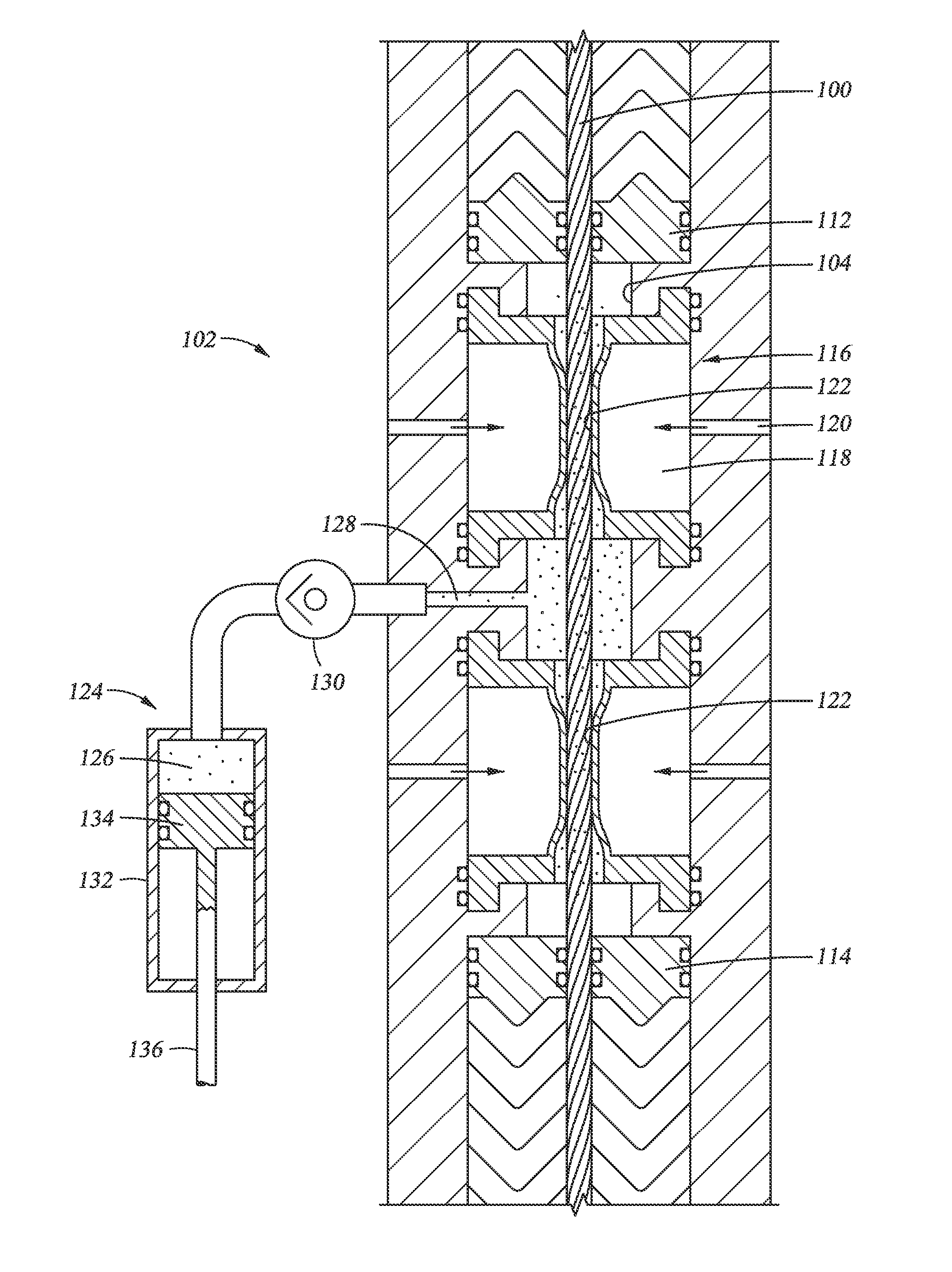
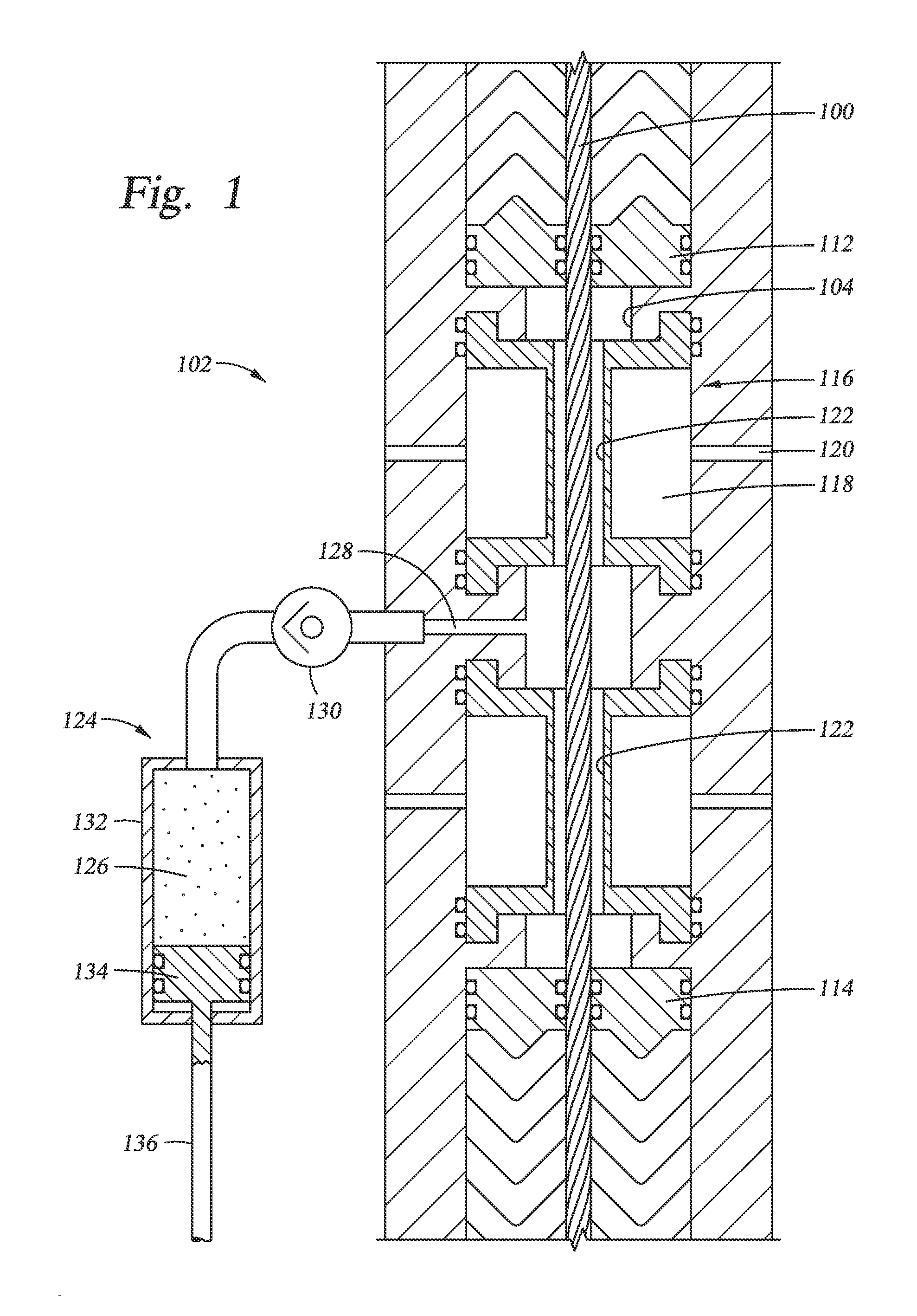
[0019]Referring to FIG. 1, cable 100 is a flexible cable suspended through pressure control head (“PCH”) 102 into a wellbore (not shown). Cable 100, which has a small diameter relative to the wellbore, can be used to lower a wireline-run tool into a wellbore. PCH 102 can be used to form a seal against cable 100 so that pressure from the wellbore is not released around ca...


PUM


Abstract

A system and method for sealing a passage around a cable is disclosed. Embodiments of the system can include an axial passage, such as a conduit and subsea wellhead housing connected to a wellbore, that can have a cable extending therethrough. The system can include an upper restrictor and a lower restrictor for closing the axial passage. An injection module having an injector and a reservoir can be fluid communication with the axial passage at an axial location between the upper restrictor and the lower restrictor. The injector can discharge a curable sealant initially stored in the reservoir into the axial passage so that at least a portion of the sealant contacts the cable at the axial location of the restrictor while the cable remains static.

Description

BACKGROUND OF THE INVENTION[0001]1. Field of the Invention[0002]The present invention relates in general to mineral recovery wells, and in particular to an apparatus and method for sealing a wellbore.[0003]2. Brief Description of Related Art[0004]Wire line operations in a wellbore typically use one of three types of wire line—slick line, e-line, or braided cable. In order to maintain pressure control during these operations, and thus prevent pressurized fluid escaping from the wellbore, the wire line is passed through a pressure controlling device. Devices for preventing pressure from escaping from the well bore include wire line blowout preventers (“BOP”), pressure control heads (“PCH”), lower riser packages (“LRP”), and lubricators.[0005]These pressure control devices employ different methods of pressure control including rams, pressure energized packing sets, and grease. These methods, although different, follow the same principals in that they all form a seal around the outside ...

Claims


Application Information

Patent Timeline
IPC IPC(8): E21B33/06E21B33/064E21B33/035E21B23/00
CPCE21B33/076E21B33/08F16J15/168F16J15/14E21B33/064E21B33/072
Inventor HUGHES, ANDREW DAVID
Owner VETCO GRAY U K
Why Eureka
Try Eureka