Transfer apparatus and method of manufacturing article

Inactive Publication Date: 2013-10-31
CANON KK
View PDF2 Cites 0 Cited by
  • Summary
  • Abstract
  • Description
  • Claims
  • Application Information

AI Technical Summary

Benefits of technology

The present invention describes a technique for aligning a pattern on an original with a shot region on a substrate. This is achieved through a transfer apparatus that includes holding units for the original, driving units for aligning the holding units with the substrate, and a control unit for controlling the driving units. The technical effect of this invention is to improve the accuracy and efficiency of pattern transfer during semiconductor device production.

Problems solved by technology

Further, the distance between the pattern portion of the original 104 and the side face of the original 104 to which a compression force is applied is long, and the controllability and efficiency of deformation are poor.

Method used


Image

  • Transfer apparatus and method of manufacturing article
  • Transfer apparatus and method of manufacturing article
  • Transfer apparatus and method of manufacturing article

Examples


Embodiment Construction

[0018]A preferred embodiment of the present invention will now be described with reference to the accompanying drawings.

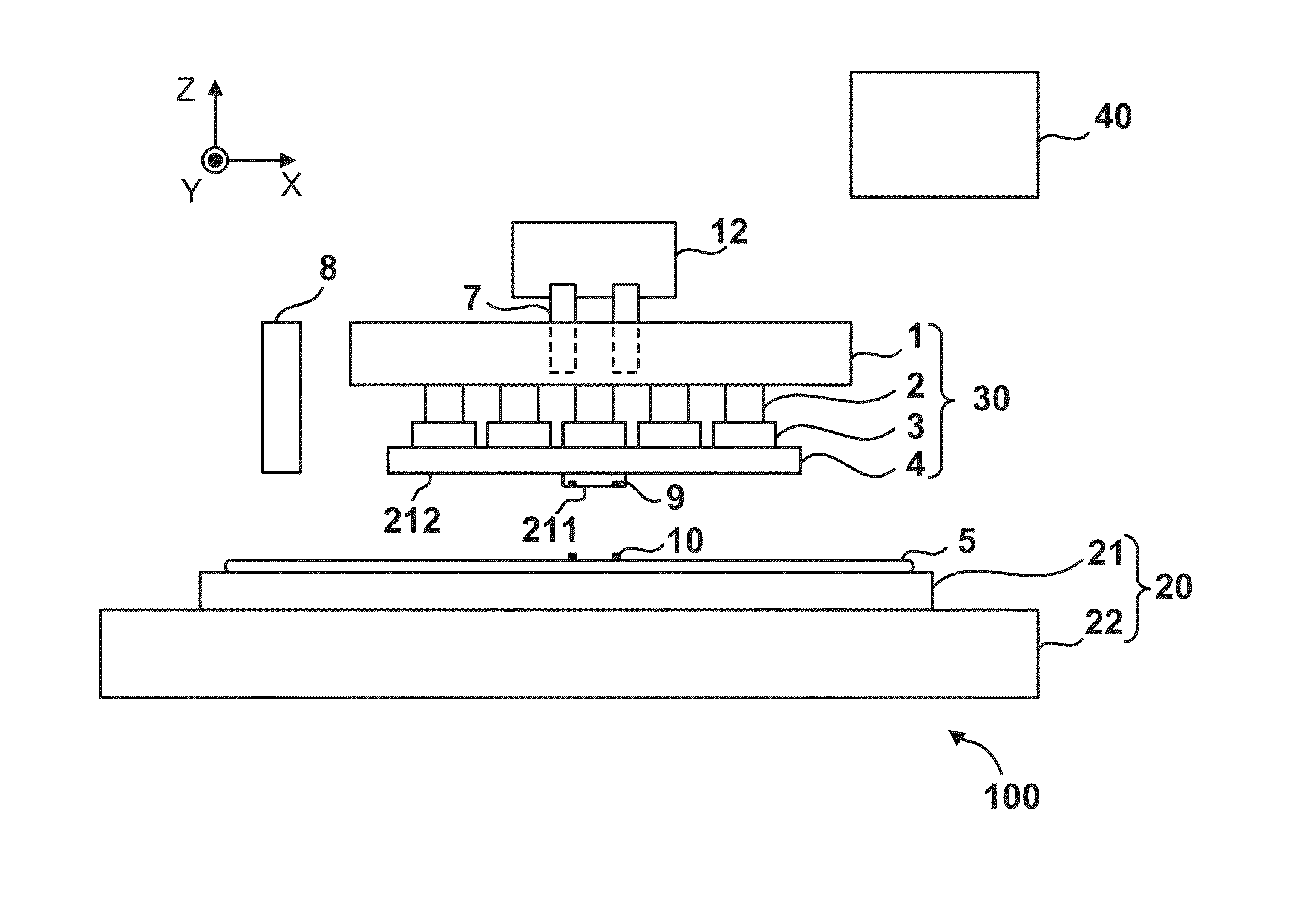
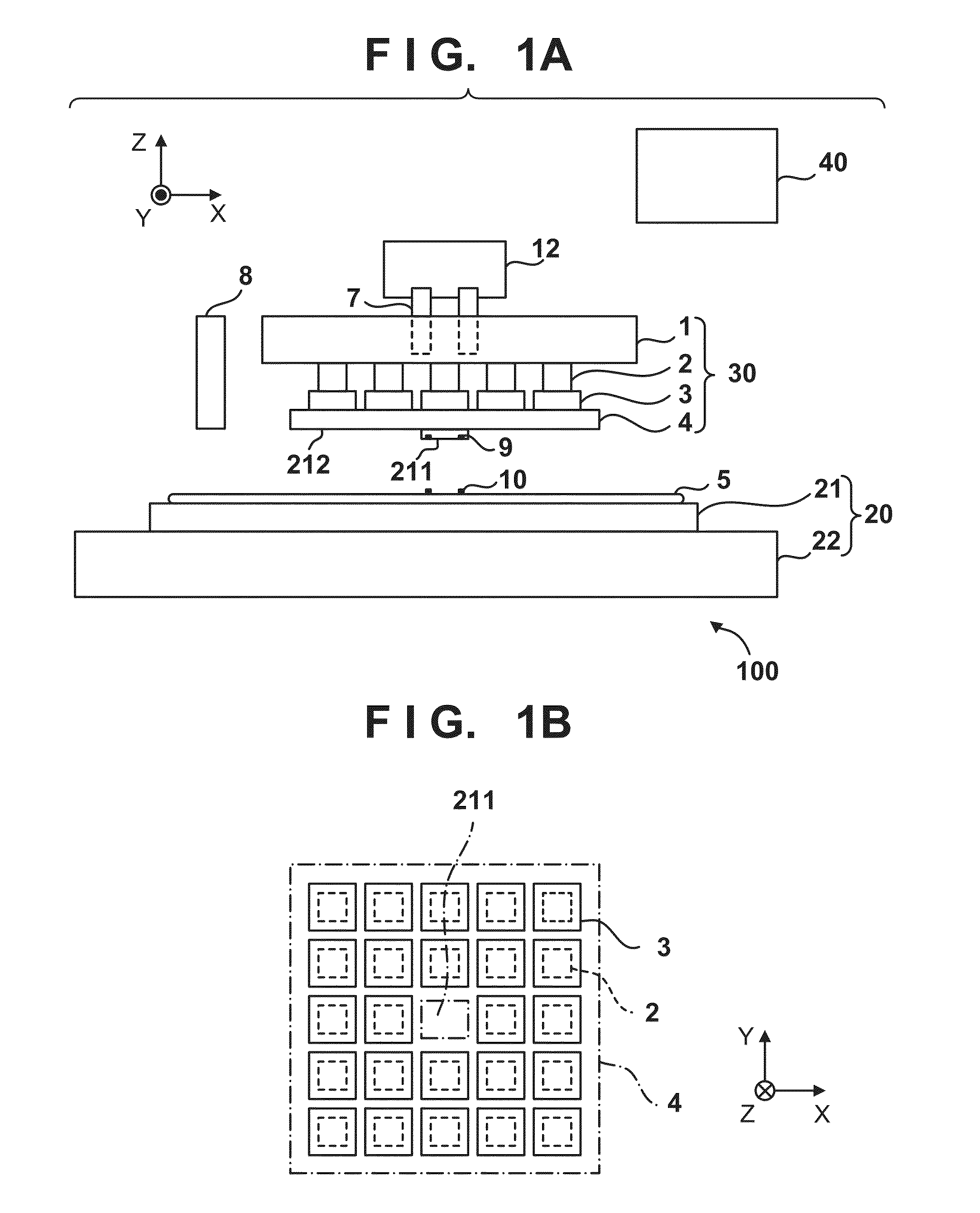
[0019]FIGS. 1A and 1B schematically show the arrangement of a transfer apparatus 100 according to one embodiment of the present invention. The transfer apparatus 100 is configured to transfer the pattern of an original 4 to a resin on a substrate 5. The transfer apparatus 100 can be configured typically as an imprint apparatus which brings the pattern region of the original 4 into contact with a resin on a shot region on the substrate 5, and cures the resin by energy applied to the resin from a curing unit 12 in this state. The curing unit 12 can be configured to, for example, cure a resin by irradiating the resin with light such as ultraviolet light. Alternatively, the curing unit 12 may be configured to cure a resin by applying heat to the resin. Although not shown in FIGS. 1A and 1B, the transfer apparatus 100 may use a reflection original 4, and project the pat...


PUM


Abstract

A transfer apparatus transfers a pattern of an original to a resin on a shot region of a substrate. The original includes a first surface and second surface which are surfaces opposite to each other. The first surface includes a pattern region where the pattern is formed, and the second surface includes a holding surface. The apparatus includes a plurality of holding units configured to hold the holding surface of the original, a plurality of driving units configured to drive the plurality of holding units, respectively, and a control unit configured to control driving of the plurality of holding units by the plurality of driving units to align the pattern region with the shot region of the substrate.

Description

BACKGROUND OF THE INVENTION[0001]1. Field of the Invention[0002]The present invention relates to a transfer apparatus which transfers the pattern of an original to a substrate, and a method of manufacturing an article.[0003]2. Description of the Related Art[0004]With recent advances in micropatterning of semiconductor devices, an imprint technique of coating a substrate with a resin and curing the resin while an original (mold) is in contact with the resin has received attention as a semiconductor device manufacturing method. In the imprint technique, it is important to reduce the alignment error between a pattern on a substrate and the pattern of an original, similar to photolithography using an exposure apparatus. In association with this, Japanese Patent Laid-Open Nos. 2007-535121 and 2008-504141 disclose techniques for applying a force to the side face of an original to deform the original.[0005]A mechanism which deforms an original, and its problem will be explained with refere...

Claims


Application Information

Patent Timeline
IPC IPC(8): B29C59/02
CPCB29C59/02G03F7/0002
Inventor YAEGASHI, KENJITAKABAYASHI, YUKIO
Owner CANON KK
Why Eureka
Try Eureka