
Method for correcting image distortion and system, and magnetic resonance imaging equipment

a magnetic resonance imaging and image distortion technology, applied in the field of magnetic resonance imaging (mri), can solve the problems of image distortion, high imaging speed of epi sequence, easy to be affected by various artifacts, etc., and achieve the effect of effectively correcting image distortion and simplifying the whole calculation process

Active Publication Date: 2013-10-31
SIEMENS HEATHCARE GMBH
View PDF2 Cites 6 Cited by
  • Summary
  • Abstract
  • Description
  • Claims
  • Application Information

AI Technical Summary

Benefits of technology

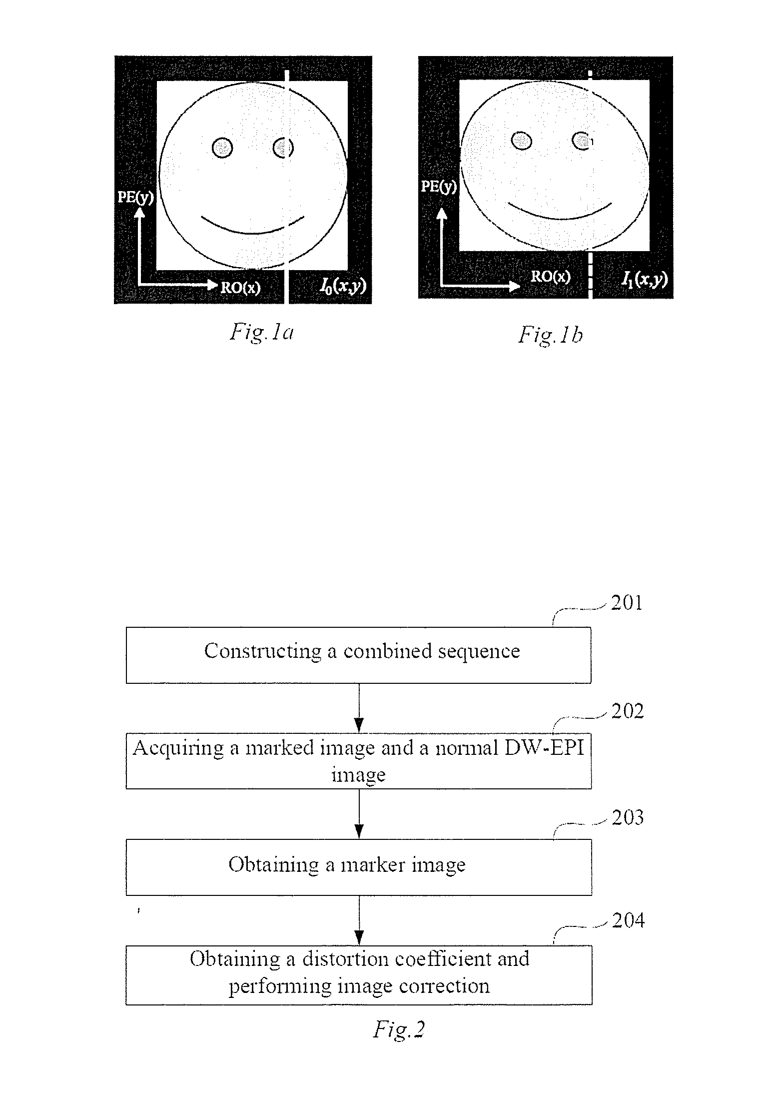
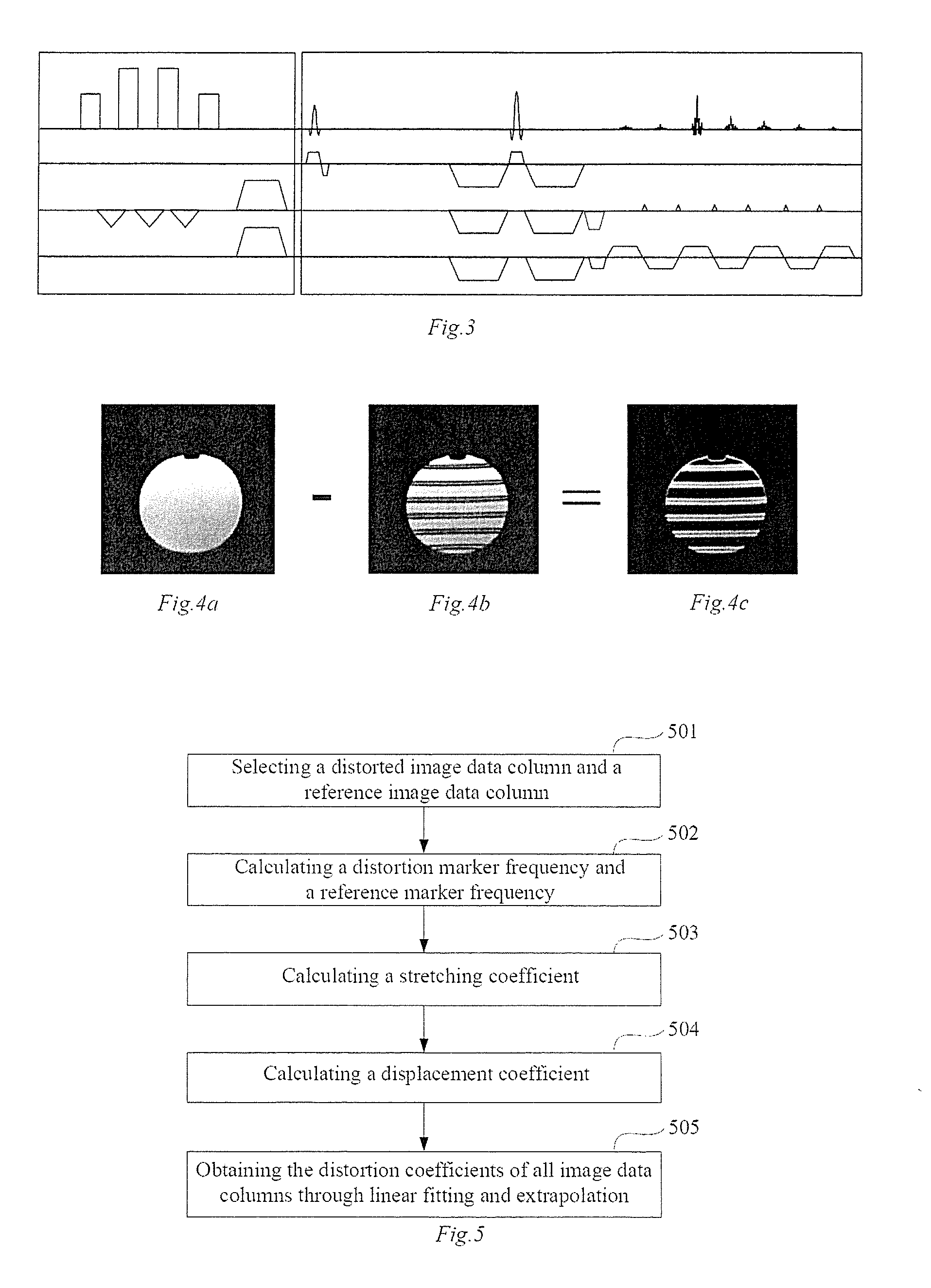
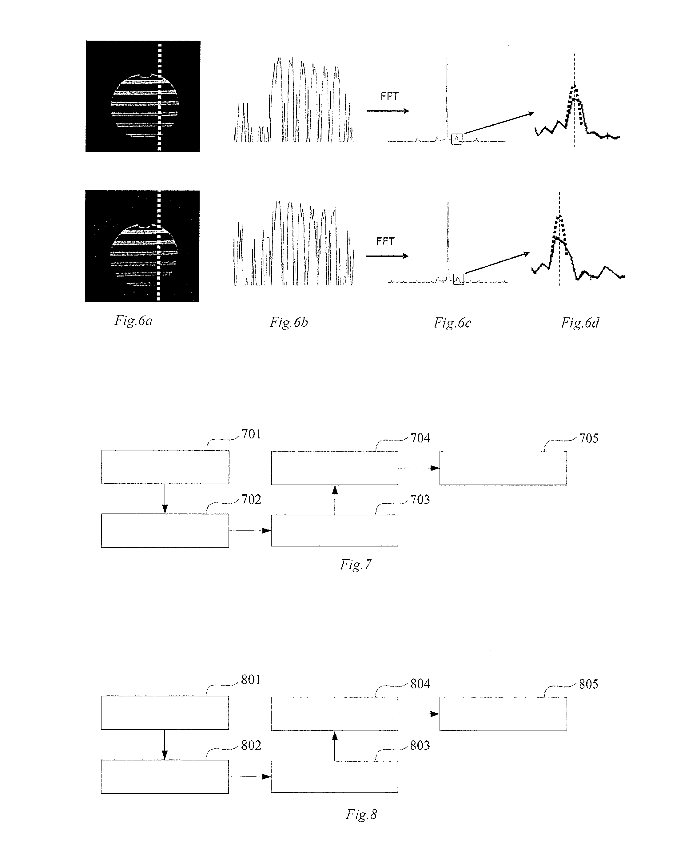
The present invention provides a method and system for correcting image distortion in DW-EPI magnetic resonance imaging. This is achieved by using a combined sequence constructed from a marker sequence and a DW-EPI sequence to obtain a marked image, which is then subtracted from a normally collected image to obtain a purely marker image. A reference marker image and a distortion marker image are used to calculate a distortion coefficient of the normally collected image, which is then utilized to correct the normally collected image. This method effectively corrects image distortion introduced by eddy current. Additionally, using a column as a unit, a plurality of reference image data columns and a plurality of distorted image data columns are selected, allowing for easier determination of image distortion. This simplifies the whole calculation process.

Problems solved by technology

Diffusion imaging is usually implemented using an echo planar imaging (EPI) sequence; the imaging speed of the EPI sequence is very high but it is easily affected by various artifacts, especially image distortion.
The diffusion gradient of the DW-EPI sequence will introduce an eddy current field into the imaging space, and the additional magnetic field of eddy current field causes image distortion.
Hence, these single images with different b values and different diffusion directions do not overlap, and if these single images are combined with each other and calculated without correction to generate isotropic DWIs and apparent diffusion coefficient (ADC) graphs and the like required in diagnosis, this will cause blurs in the DWI and errors in the calculation of the ADC graphs, and the like.
These methods can be used to effectively reduce but cannot completely eliminate the influence of the eddy current field.

Method used


Image

  • Method for correcting image distortion and system, and magnetic resonance imaging equipment
  • Method for correcting image distortion and system, and magnetic resonance imaging equipment
  • Method for correcting image distortion and system, and magnetic resonance imaging equipment

Examples


example i

[0134]The particular imaging parameters of DW-EPI imaging are: 1.5T magnetic resonance imager, TE / TR=127 / 500 msec; bandwidth: 1000 Hz; field of view (FoV): 200×200 mm; imaging matrix: 128×128; layer thickness: 1; average passes: 4; the b values used in diffusion imaging are respectively: 0, 500, 1000; diffusion mode: orthogonal; and diffusion method: single polarity.

[0135]Most of the particular imaging parameters of a marked image are the same as those of a DW-EPI image, except that the average pass is 1.

[0136]FIGS. 9a to 9g show schematic diagrams of distortion correction for an image with b=1000. FIG. 9a is an image with b=0; FIGS. 9b to 9d are images with b=1000 in three different diffusion directions; FIG. 9b is an image in the direction of phase coding, FIG. 9c is an image in the direction of readout, and FIG. 9d is an image in the slice selective direction. FIGS. 9e to 9g are images after correction in each diffusion direction in FIGS. 9b to 9d respectively, wherein FIG. 9e is...

example ii

[0140]The particular imaging parameters of DW-EPI imaging are: 3T magnetic resonance imager, TE / TR=108 / 5900 msec; bandwidth: 1040 Hz; field of view (FoV): 235×235 mm; imaging matrix: 192×192; layer thickness: 25; average passes: 4; the b values used in diffusion image are respectively: 0, 1000; diffusion mode: orthogonal; and diffusion method: single polarity.

[0141]Most of the particular imaging parameters of a marked image are the same as those of a DW-EPI image, except that the average pass is 1.

[0142]FIGS. 12a to 12g show results of distortion correction for an image with b=1000. FIG. 12a is an image with b=0; FIGS. 12b to 12d are images with b=1000 in three different diffusion directions; FIG. 12b is an image in the direction of phase coding, FIG. 12c is an image in the direction of readout, and FIG. 12d is an image in the slice selective direction. FIGS. 12e to 12g are images after correction in each diffusion direction in FIGS. 12b to 12d respectively, wherein FIG. 12e is an i...


PUM


Abstract

In a method for an apparatus correcting image distortion in diffusion-weighted echo-planar magnetic resonance imaging, a marker sequence is applied before a diffusion-weighted echo planar imaging sequence, to form a combined sequence. The combined sequence is used to obtain marked images with different preset b values and different preset diffusion directions. The diffusion-weighted echo planar imaging sequence is used to obtain diffusion-weighted echo planar images with the same b values and diffusion directions as the marked images. A stretching coefficient and a displacement coefficient are calculated for each image data column of the diffusion-weighted echo planar image. The stretching coefficient and displacement coefficient are used to correct the diffusion-weighted echo planar images.

Description

BACKGROUND OF THE INVENTION[0001]1. Field of the Invention[0002]The present invention relates to the technical field of magnetic resonance imaging (MRI), and particularly to a method for correcting image distortion and system for diffusion-weighted echo planar imaging (DW-EPI) and magnetic resonance imaging equipment.[0003]2. Description of the Prior Art[0004]Diffusion imaging is a functional magnetic resonance imaging technology which has very high clinical importance, which can detect the biological properties of the diffusion of water molecules in human tissue and thus detect many pathologies which cannot be found by conventional medical imaging means. Diffusion imaging is usually implemented using an echo planar imaging (EPI) sequence; the imaging speed of the EPI sequence is very high but it is easily affected by various artifacts, especially image distortion.[0005]Diffusion-weighted imaging (DWI) is an important imaging method of diffusion imaging, which is usually implemented...

Claims


Application Information

Patent Timeline
IPC IPC(8): G01R33/565
CPCG01R33/56572G01R33/56341G01R33/56518
Inventor ZHOU, KUN
Owner SIEMENS HEATHCARE GMBH
Learn More