
Ink jet recording method and ink jet recording apparatus

Active Publication Date: 2013-10-31
SEIKO EPSON CORP
View PDF6 Cites 25 Cited by
  • Summary
  • Abstract
  • Description
  • Claims
  • Application Information

AI Technical Summary

Benefits of technology

This patent is about an ink jet recording method that has better curing and stability, and reduces the internal temperature of the recording apparatus after continuous printing. By using an ultraviolet ray-curable ink with low viscosity and an appropriate discharge temperature, the method achieves high-quality images. The method includes discharging the ink onto a recording medium and then curing it with ultraviolet rays. The technical effect of this invention is to provide a more efficient and stable ink jet recording method with improved curability and discharge stability.

Problems solved by technology

However, when ink jet recording is performed using the energy ray-curable ink composition disclosed in Japanese Patent No. 4335955, there are problems in that curability and discharge stability deteriorate; and that image quality stability deteriorates due to a significant increase in the internal temperature of a recording apparatus after continuous printing (continuous discharge).
However, since the acrylic equivalent of the entire ink composition is not specified, reaction heat generated during the curing of ink is not considered.
As a result, ink application positions or the amount of ink discharged may be changed and thus the image quality of an obtained image is not stable in terms of graininess, hue, and the like.
As described above, when the ink composition disclosed in Japanese Patent No. 4335955 is used for a relatively long-period recording such as continuous printing, it is difficult to satisfy superior curability and discharge stability at the same time and to perform recording.
However, in this case, there is a problem in that the internal temperature of an ink jet recording apparatus is significantly increased.
This case also has a problem in that the internal temperature of the ink jet recording apparatus is significantly increased.

Method used


Image

  • Ink jet recording method and ink jet recording apparatus
  • Ink jet recording method and ink jet recording apparatus
  • Ink jet recording method and ink jet recording apparatus

Examples


example 1

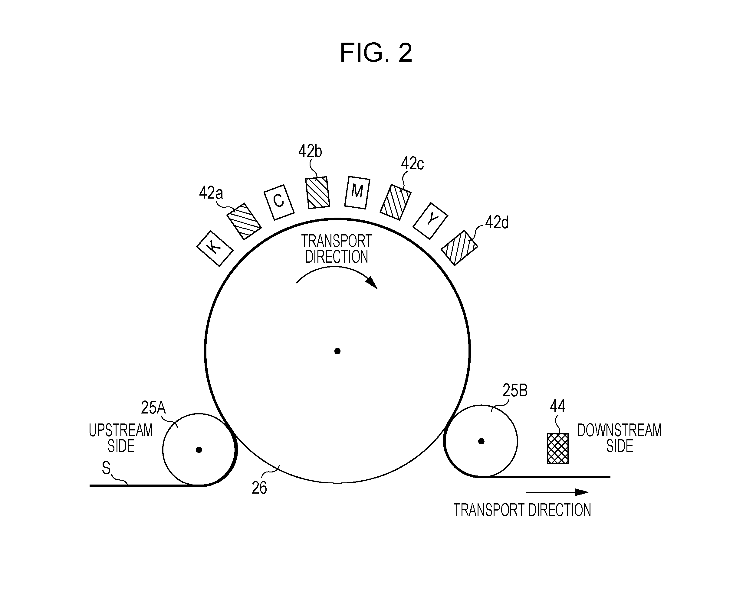
[0181]The line printer illustrated in FIG. 2 was used in which four line heads having a length substantially equal to a width (recording width) of a recording surface, on which an image is to be recorded, were arranged in parallel in the width direction. Among the heads and light sources in FIG. 2, the head C and the light sources 42b and 44 were used; and the other heads and light sources were not used.

[0182]The transport drum 26 was made of aluminum; the diameter of the transport 26 was 500 mm; the printing speed was 285 mm / s; and the drum rotation period was 5.5 s.

[0183]The ink 1 shown in Table 2 was continuously discharged for 10 minutes (continuous printing was performed for 10 minutes) from the head C having a nozzle density of 600 dpi onto the PET film (PET 50 (K2411) PA-T1 8LK) under conditions of a recording resolution of 600 dpi×600 dpi and one pass (single pass). The amount of ink droplets per pixel was adjusted such that the thickness of the cured film was 11 μm. In Exam...

example 8

[0187]A recorded material was obtained in the same method as that of Example 1, except that the diameter of the transport drum 26 was 318 mm and the drum rotation period was 3.5 s (printing speed was the same as that of Example 1).

example 9

[0188]A recorded material was obtained in the same method as that of Example 1, except that a metal halide lamp (in Table 2, abbreviated as “MHL”) was used as the light source 42b instead of a LED.


PUM


Abstract

Provided is an ink jet recording method including: discharging an ultraviolet ray-curable ink, which has a viscosity at 20° C. of 25 mPa·s or less and an average equivalent of polymerizable unsaturated double bond of 100 to 150, from a head onto a recording medium at a discharge temperature of 30° C. to 40° C.; and irradiating the ultraviolet ray-curable ink, attached onto the recording medium, with ultraviolet rays emitted from a light source to cure the ultraviolet ray-curable ink.

Description

BACKGROUND[0001]1. Technical Field[0002]The present invention relates to an ink jet recording method and an ink jet recording apparatus.[0003]2. Related Art[0004]In the related art, various methods are used as a recording method of forming an image on a recording medium such as paper based on image data signals. Among these methods, when an ink jet method is used, ink can be discharged onto only a desired image portion of a recording medium with an inexpensive apparatus and an image is directly formed on the recording medium. Therefore, ink can be efficiently used and running cost is low. Furthermore, little noise is made in the ink jet method, which is superior as a recording method.[0005]Recently, an ink jet recording method using a photocurable ink in which monomers are photopolymerized (cured) by irradiation of light has been disclosed. With this ink jet method, an image having superior water resistance and wear resistance can be formed on a recording surface of a recording medi...

Claims


Application Information

Patent Timeline
IPC IPC(8): B41J2/01
CPCB41J2/01B41J2/0057B41J11/00214C09D11/101C09D11/30B41J2/2107
Inventor FUKUMOTO, HIROSHIKIDA, HIROAKI
Owner SEIKO EPSON CORP
Learn More