
Apparatus and methods for microscopy having resolution beyond the Abbe limit

a microscopy and abbe limit technology, applied in the field of microscopy, can solve the problems of limited resolution, limited resolving ability of microscopy, and limited na maximum value, etc., and achieve the effect of reducing the amount of fluorescing area, and increasing the potential resolution

Inactive Publication Date: 2013-10-31
PERIODIC STRUCTURES
View PDF4 Cites 30 Cited by
  • Summary
  • Abstract
  • Description
  • Claims
  • Application Information

AI Technical Summary

Benefits of technology

This patent describes a microscope and methods with better resolution than standard microscopes. The microscope uses two different wavelengths of light to capture images of an object. One wavelength is used to inhibit fluorescence, while the other wavelength is used to activate the fluorescence. By measuring the interference pattern created by the two wavelengths, the microscope can create high-resolution images. The sensor used to capture the images is designed to reduce the effects of individual detector elements, creating larger sections of the image that are analyzed. Overall, this technology allows for better details and higher resolution in microscopic images.

Problems solved by technology

Microscopes, like all image-forming optical instruments, have limited resolving ability (“resolution”) even if the optical components are made perfectly.
The limited resolution is due to diffraction that occurs at the aperture stop or pupil of the instrument.
However, the maximum value of the NA is limited by the index of refraction of available immersion liquids (oil and water being generally preferred) and the maximum value of the sine function, which is unity.
This is achieved only with great difficulty and under very special conditions.
Diffraction is a fundamental part of image formation and cannot be avoided.

Method used


Image

  • Apparatus and methods for microscopy having resolution beyond the Abbe limit
  • Apparatus and methods for microscopy having resolution beyond the Abbe limit
  • Apparatus and methods for microscopy having resolution beyond the Abbe limit

Examples


numerical example

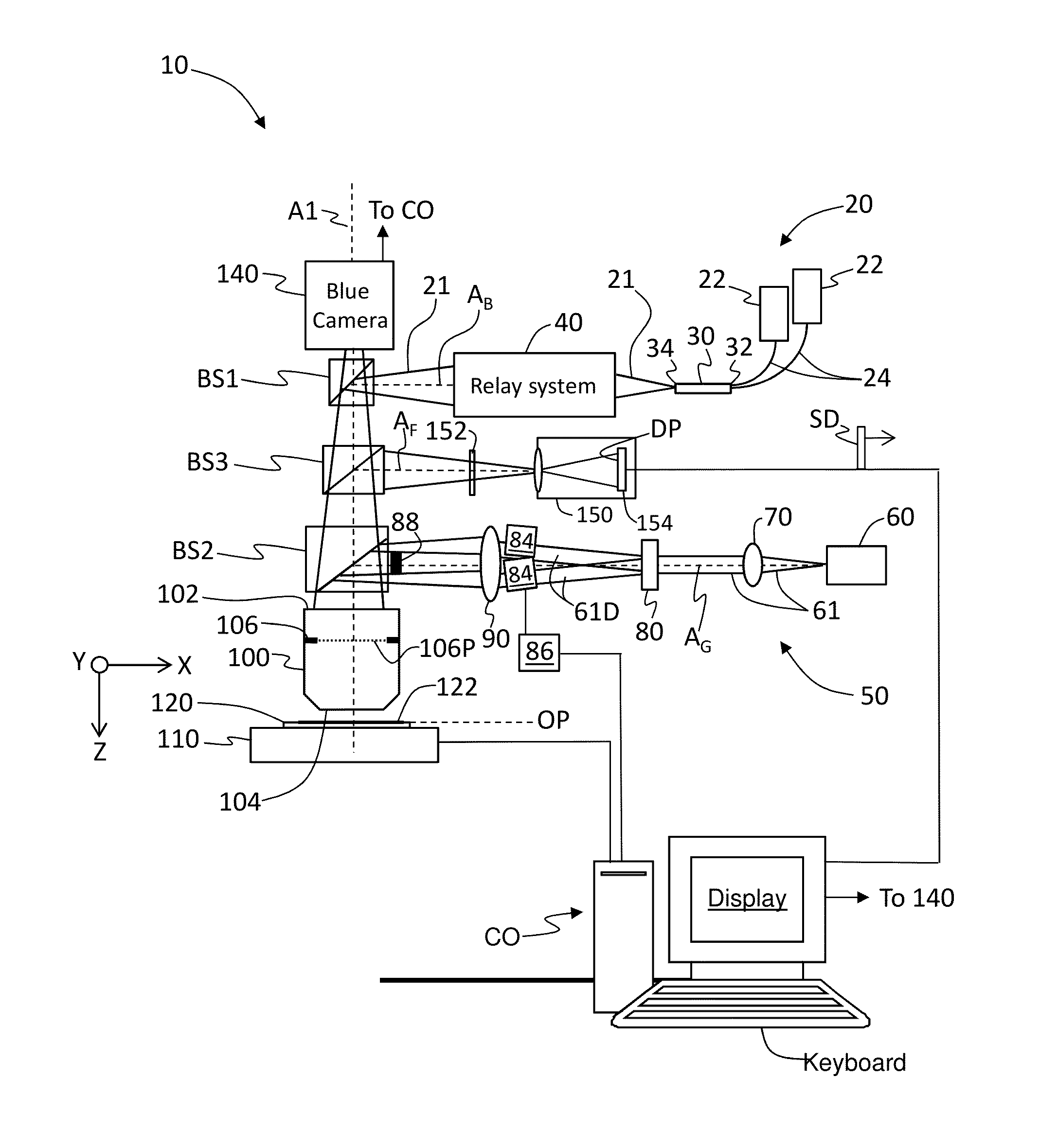
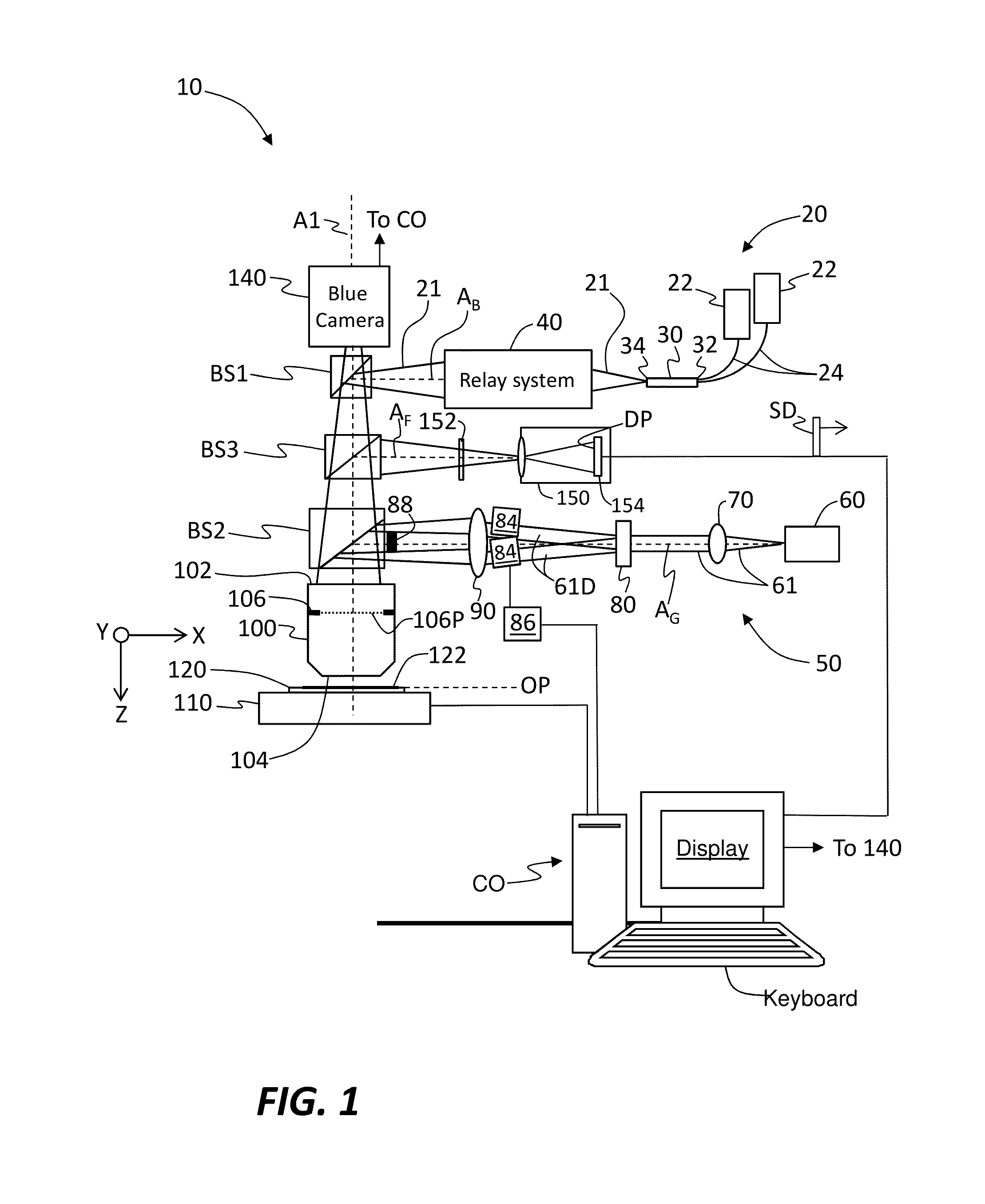
[0118]A numerical example is now presented as based on the following assumptions:

Size of photodetector 154 (detector array): 1,024 by 1,024 detector elements DE

Size of individual detector element DE: 3×3 microns

Green (inhibition) wavelength λ2=532 nm

Blue (activation) wavelength λ1=405 nm

Objective lens NA=0.9

Resolution required=25 nm

The green and blue intensity values c·G and B can be obtained from the equation for resolution, namely: IW′=(λ2 / π·NA)·arcsin((0.6B / cG)0.5)

25 nm=(532 nm / π·0.9)arcsin((0.6·B / cG)0.5))→c·G / B=33.8

[0119]To obtain a resolution of 25 nm, it is necessary to have a green-to-blue intensity ratio cG / B=33.8. This assumes that the fluorescence generated by one watt of 405-nm blue light will be suppressed by the equivalent of one watt of 532-nm green light. The equivalence depends on the value of the constant c.

[0120]This improvement in resolution is achieved by reducing the size of the emitting areas 124 on object 122 and is not directly seen on photodetector 154. The ...


PUM

PropertyMeasurementUnit
wavelengthaaaaaaaaaa
activation wavelengthaaaaaaaaaa

Abstract

Microscope apparatus and methods for imaging an object with a resolution beyond the Abbe limit are disclosed. The apparatus employs an object selectively patterned with a fluorescing material that is induced to fluoresce with one wavelength and inhibited from fluorescing with a second wavelength. Two orthogonal interference-fringe patterns are generated from four diffracted light beams of an inhibiting wavelength and superimposed on the object along with light that induces fluorescence. The interference-pattern image allows only sub-resolution-sized emission areas of the object to fluoresce. Multiple images of the fluorescing object are obtained, each corresponding to a slightly different position of the fringe patterns on the substrate. Each image is processed to yield a sparsely sampled super-resolution image. Multiple sparse images are interwoven to form a complete super-resolution image of the object.

Description

CLAIM OF PRIORITY & CROSS-REFERENCE TO RELATED APPLICATIONS[0001]This application claims priority under 35 U.S.C. §119(e) from U.S. Provisional Application Ser. No. 61 / 639,947, filed on Apr. 29, 2013, which application is incorporated by reference herein.[0002]This application is related to U.S. patent application Ser. No. 13 / 678,692, filed on Nov. 16, 2012, and which is incorporated by reference herein.FIELD[0003]The present disclosure relates to microscopy, and in particular microscopy apparatus and methods that have a resolution beyond the Abbe limit.BACKGROUND ART[0004]Microscopes, like all image-forming optical instruments, have limited resolving ability (“resolution”) even if the optical components are made perfectly. The limited resolution is due to diffraction that occurs at the aperture stop or pupil of the instrument. This fundamental phenomenon was first explained in 1873, by Ernst Karl Abbe. Abbe explained that the smallest possible image that can be formed by a microsco...

Claims


Application Information

Patent Timeline
Patent Type & Authority Applications(United States)
IPC IPC(8): G01N21/64
CPCG01N21/6458
Inventor MARKLE, DAVID A.JEONG, HWAN J.PETERSEN, JOHN S.
Owner PERIODIC STRUCTURES
Learn More