
Projector

Inactive Publication Date: 2013-10-31
SEIKO EPSON CORP
View PDF4 Cites 15 Cited by
  • Summary
  • Abstract
  • Description
  • Claims
  • Application Information

AI Technical Summary

Benefits of technology

The patent describes a projector that uses a laser light source and a dichroic film to combine two light components in a way that reduces fringe patterns and image degradation. This results in a better projected image. The use of a diffuser member with two light diffusing portions also helps to reduce interference and improve optical quality.

Problems solved by technology

Depending on a projection environment, such a pattern is highly visible, resulting in image degradation in some cases.
Laser light is a light component that can cause image degradation due, for example, to interference, such as generation of a fringe pattern on a screen.

Method used


Image

  • Projector
  • Projector
  • Projector

Examples


Embodiment Construction

[0023]A projector according to an embodiment of the invention will be described below in detail with reference to the drawings.

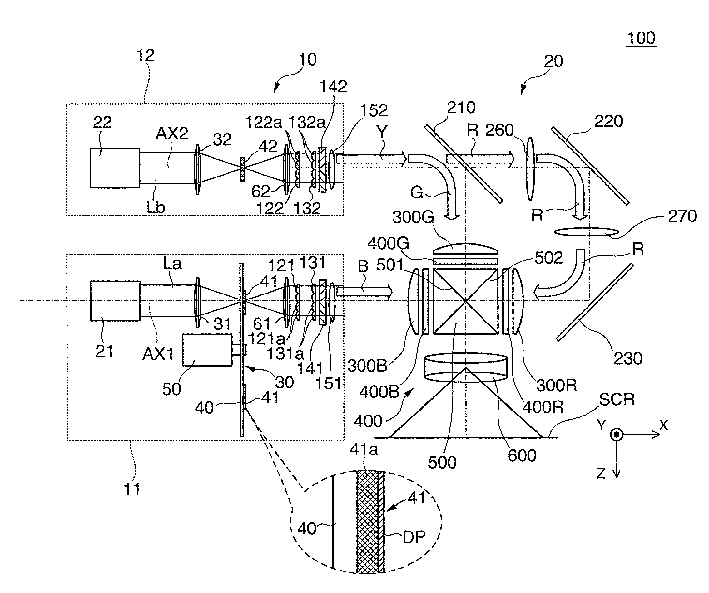
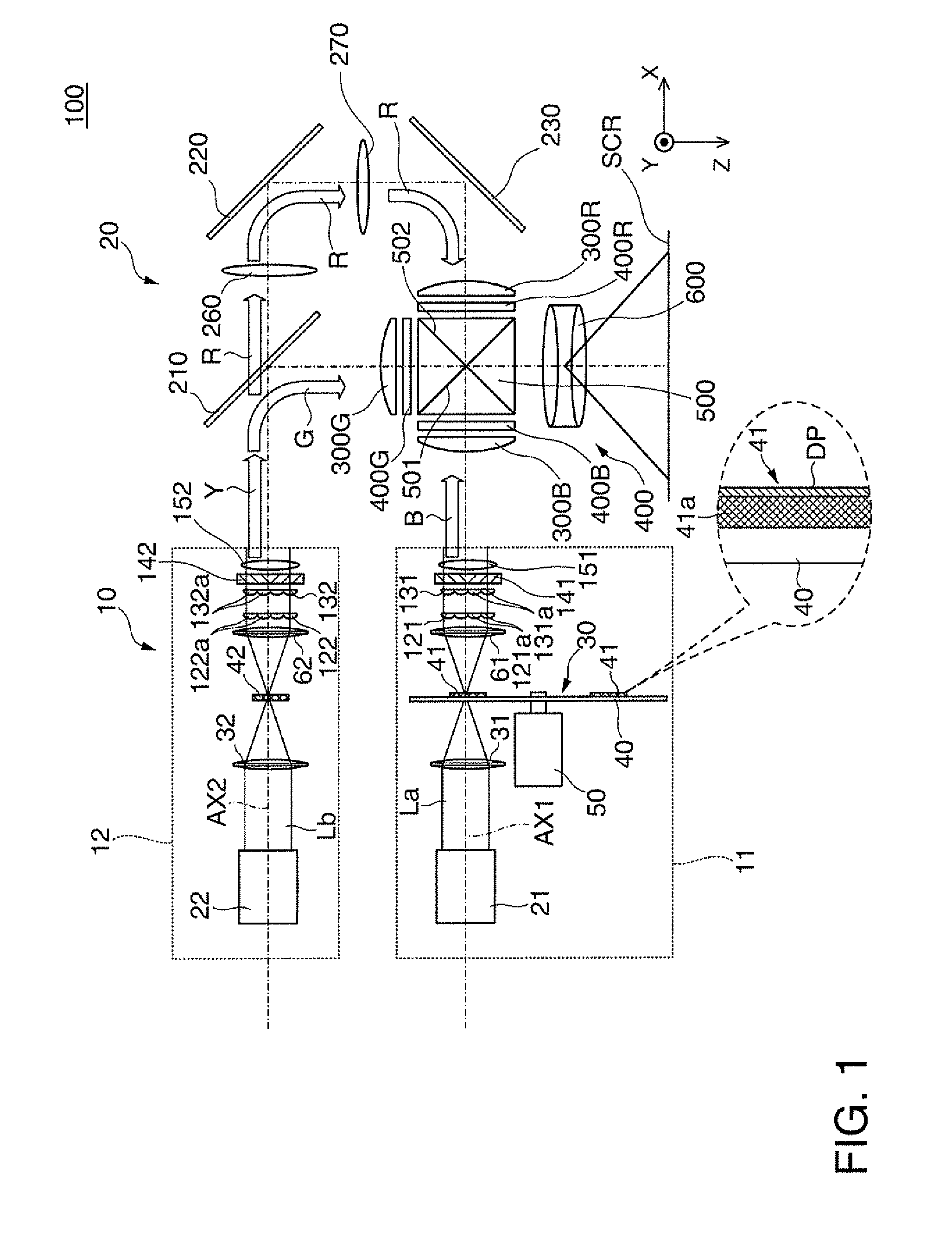
[0024]A projector 100 shown in FIG. 1 includes a light source apparatus 10, a color separation / light guiding system 20, a light modulation unit 400, a cross dichroic prism 500, which is a light combining system, and a projection system 600. In the projector 100, field lenses 300R, 300G, and 300B are disposed between the color separation / light guiding system 20 and the light modulation unit 400.

[0025]The light source apparatus 10 is formed of two light source units, a first light source unit 11 and a second light source unit 12, each of which outputs illumination light. The first light source unit 11, as part of the light source apparatus 10, outputs blue light as first light that contains part of the entire wavelength components of the illumination light. Similarly, the second light source unit 12, as part of the light source apparatus 10, outputs yellow lig...


PUM


Abstract

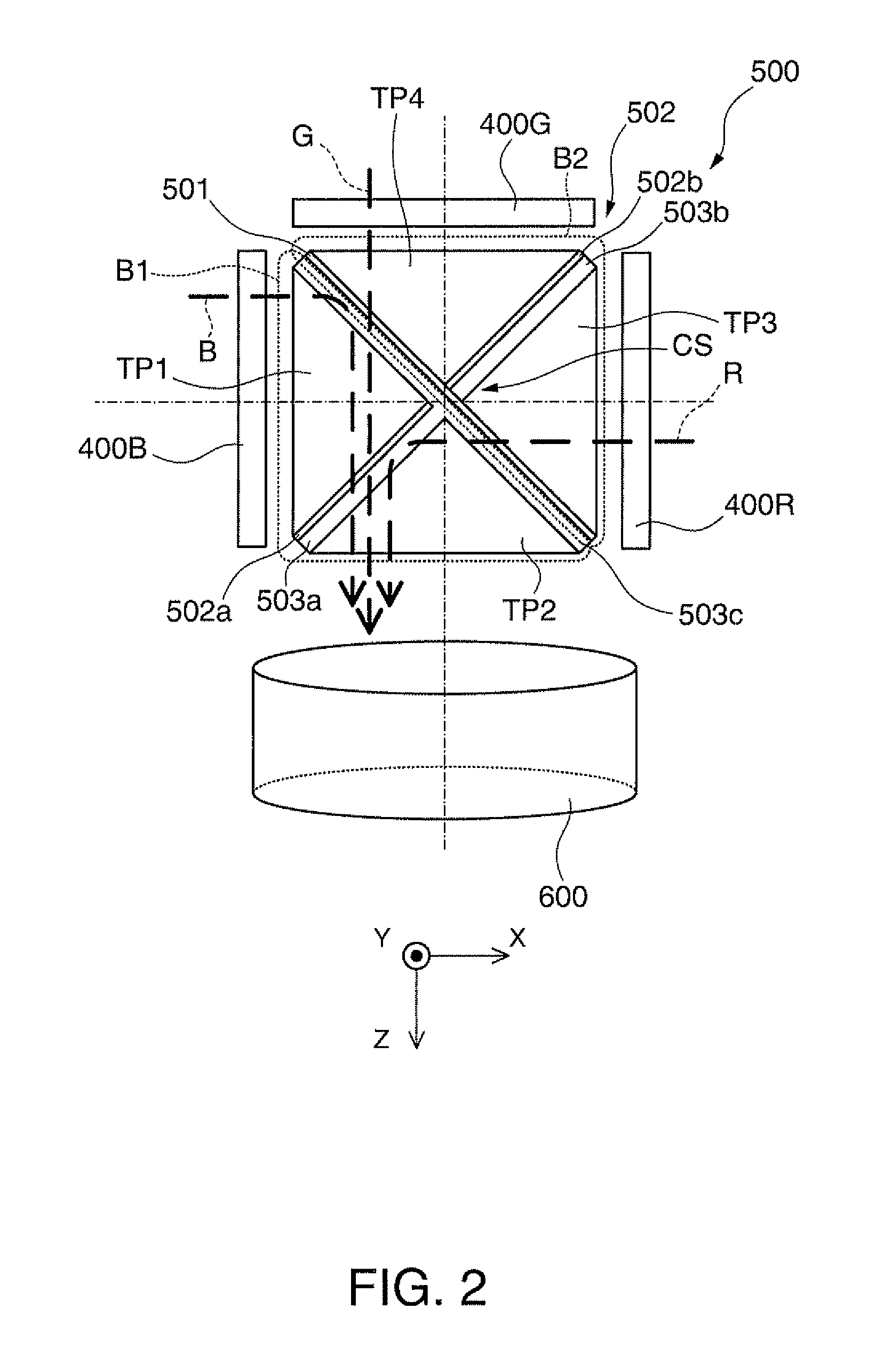
Even when coherent light (specific light), such as laser light, is used as a light source, providing a first dichroic film having a seamless, single-film configuration as a film in a cross dichroic prism prevents a fringe pattern resulting from a highly interfering component contained in light combined in the cross dichroic prism from being produced, whereby the amount of image degradation can be reduced.

Description

BACKGROUND[0001]1. Technical Field[0002]The present invention relates to a projector including a laser light source or any other light source that produces interfering light, light that causes interference, to form a color image that is a combination of images of different colors.[0003]2. Related Art[0004]There is a known projection-type display apparatus, such as a projector, including a cross dichroic prism to form a color image (see JP-A-2002-189109, JP-A-2007-58008, and JP-A-11-352440, for example). It is also known in a projector using a cross dichroic prism that one of the dichroic films therein has a single-film configuration (see JP-A-2002-189109, JP-A-2007-58008, and JP-A-11-352440).[0005]On the other hand, there is a known projector that uses laser light as a light source (see JP-A-2007-33578 and JP-A-2011-128482, for example). In JP-A-2007-33578, for example, a diffuser optical element is used to diffuse the laser light to form uniform illumination light for illumination,...

Claims


Application Information

Patent Timeline
IPC IPC(8): G03B21/28
CPCG03B21/28G02B27/48G03B21/204G03B21/2066G03B21/2073G03B21/208G03B33/12H04N9/3161H04N9/3164
Inventor KAWAMURA, MASAKAZUYOSHIDA, KANJIHASHIMOTO, AKIRAMATSUBARA, TAKAYUKI
Owner SEIKO EPSON CORP
Learn More