Apparatus and method for dynamic spectral filtration

a dynamic spectral filter and apparatus technology, applied in the field of diagnostic imaging, can solve the problems of limited energy separation between samples, little opportunity to change the filtering between samples, and typical systems that do not include the ability to discriminate the spectral energy content of x-rays, etc., to achieve the effect of increasing energy separation and increasing energy separation

Inactive Publication Date: 2013-10-31
GENERAL ELECTRIC CO
View PDF0 Cites 12 Cited by
  • Summary
  • Abstract
  • Description
  • Claims
  • Application Information

AI Technical Summary

Problems solved by technology

Such typical systems, however, do not include an ability to discriminate spectral energy content of x-rays as they pass through an object being imaged.
While acquisition in such an interleaved fashion advantageously provides close temporal registration between the 2 kV datasets so as to minimize artifacts due to patient motion, a drawback to the interleaved acquisition is that, because the switching occurs very rapidly on a single x-ray source, there is little opportunity to change the filtration between the two samples.
As a result, there is a spectral (energy) overlap between the two samples that inherently limits the amount of energy separation between them.
However, it is not feasible to simply decrease the low kVp or increase the high kVp in order to increase energy separation therebetween.
Lowering the low kVp may have limited signal-to-noise and cause other limitations in image reconstruction, with most x-rays get absorbed at lower kV settings (i.e., higher absorbed dose) so as to not make it to the detector.
Increasing the high kVp may cause system instability and spit activity and may cause other limitations in system operation, with higher kV also yielding less contrast since fewer x-rays interact with object being imaged.

Method used


Image

  • Apparatus and method for dynamic spectral filtration
  • Apparatus and method for dynamic spectral filtration
  • Apparatus and method for dynamic spectral filtration

Examples


Embodiment Construction

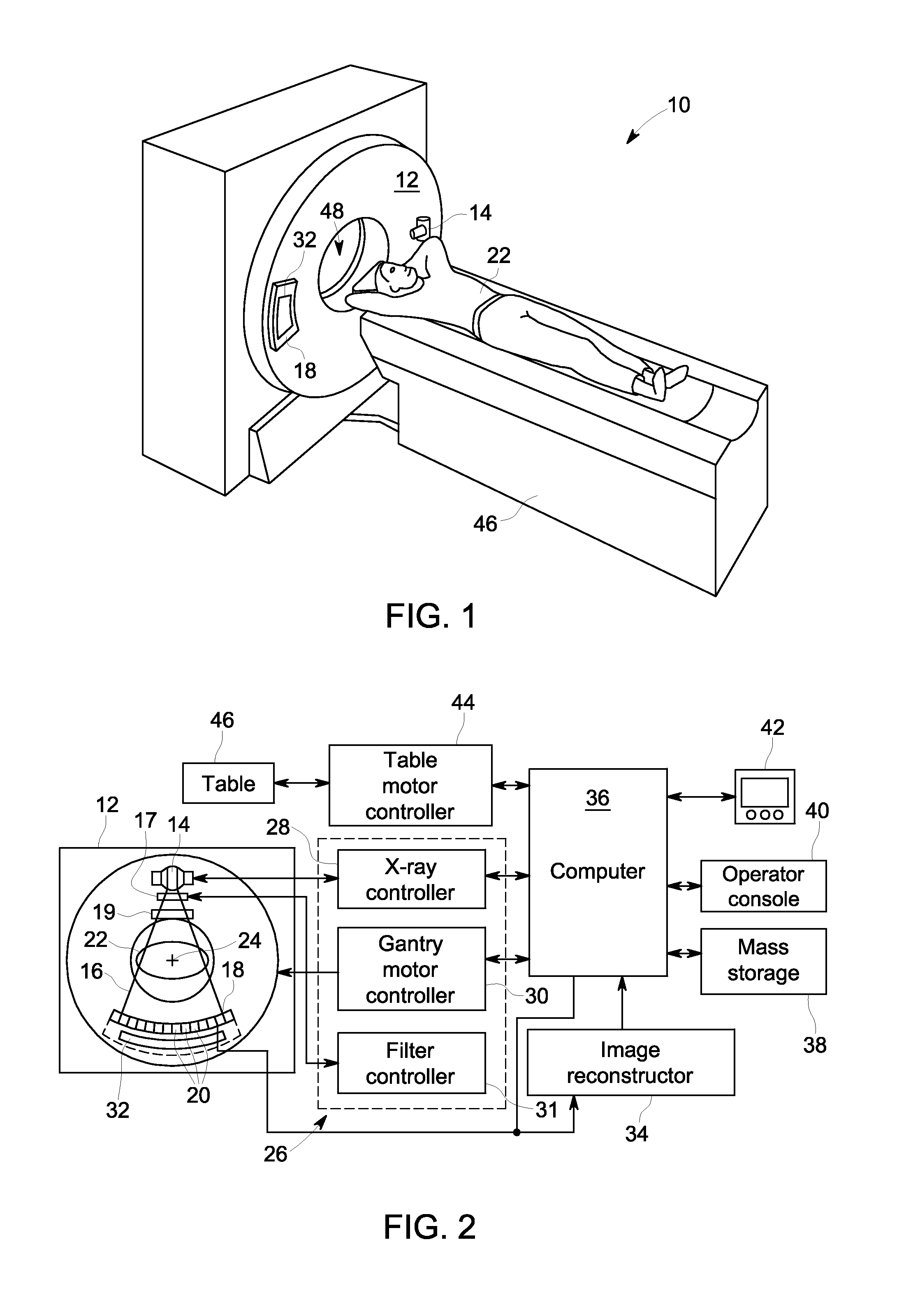
[0026]The operating environment of the present invention is described with respect to a sixty-four-slice computed tomography (CT) system. However, it will be appreciated by those skilled in the art that the invention is equally applicable for use with other multi-slice configurations. Moreover, the invention will be described with respect to the detection and conversion of x-rays. However, one skilled in the art will further appreciate that the invention is equally applicable for the detection and conversion of other high frequency electromagnetic energy. The invention will be described with respect to a “third generation” CT scanner, but is equally applicable with other CT systems.

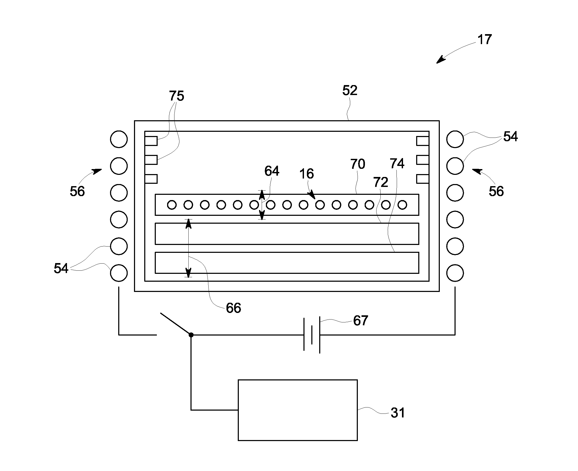
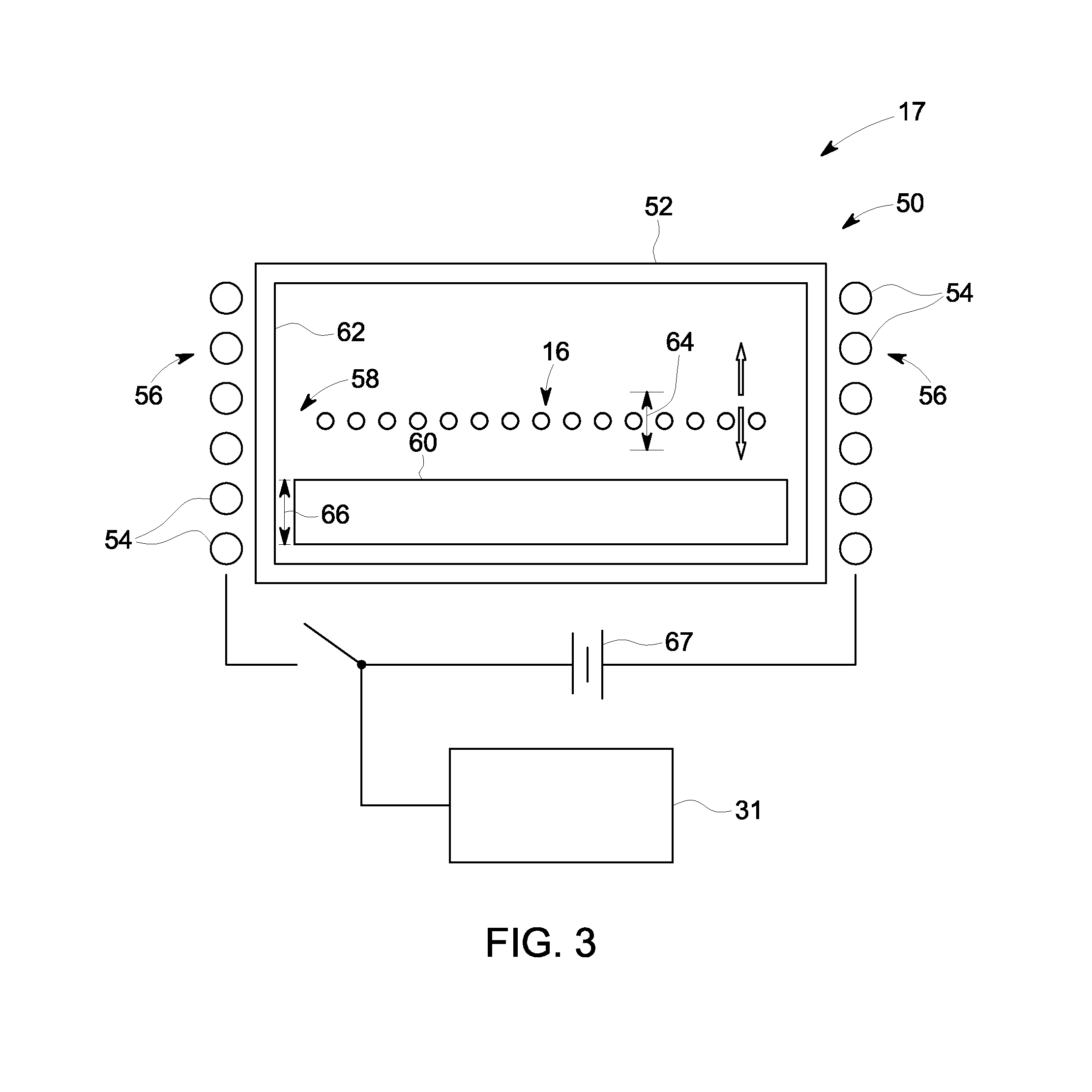
[0027]Referring to FIGS. 1 and 2, a computed tomography (CT) imaging system 10 is shown as including a gantry 12 representative of a “third generation” CT scanner. Gantry 12 has an x-ray source 14 that projects a beam of x-rays 16 through a dynamically controlled multi-position spectral filter 17 and towa...


PUM

PropertyMeasurementUnit
fan angleaaaaaaaaaa
fan angleaaaaaaaaaa
thicknessaaaaaaaaaa

Abstract

A CT imaging system includes a multi-position x-ray filter having a filter element configured to spectrally filter a beam of x-rays and a magnet structure configured to selectively generate a magnetic field to cause the filter element to move between filter and non-filter positions. A CT imaging system computer causes an x-ray source to emit x-rays at each of a first kVp and a second kVp and control the multi-position x-ray filter to position the filter element in the non-filter position during emission of the x-rays at the first kVp and in the filter position during emission of the x-rays at the second kVp. The computer causes current to be provided to the magnet structure so as to generate a magnetic field configured to move the filter element to the filter and non-filter positions at high frequency, into and out of a path of the beam of x-rays.

Description

BACKGROUND[0001]The present invention relates generally to diagnostic imaging and, more particularly, to a system and method for dynamic spectral filtration for providing an increased separation of mean energies between low and high kVp image acquisitions.[0002]Medical imaging devices comprise x-ray systems, magnetic resonance (MR) systems, ultrasound systems, computed tomography (CT) systems, positron emission tomography (PET) systems, ultrasound, nuclear medicine, and other types of imaging systems. Typically, in CT imaging systems, an x-ray source emits a fan-shaped beam toward a subject or object, such as a patient or a piece of luggage. Hereinafter, the terms “subject” and “object” shall include anything capable of being imaged. The beam, after being attenuated by the subject, impinges upon an array of radiation detectors. The intensity of the attenuated beam radiation received at the detector array is typically dependent upon the attenuation of the x-ray beam by the subject. E...

Claims


Application Information

Patent Timeline
Patent Type & Authority Applications(United States)
IPC IPC(8): A61B6/03G01N23/04G21K3/00
CPCA61B6/03G01N23/046G01N2223/313A61B6/482G21K1/10G01N2223/419G01N2223/612
Inventor ROGERS, CAREY SHAWN
Owner GENERAL ELECTRIC CO
Why Eureka
Try Eureka