Method and system for improving the visibility of features of an image

a technology of image features and display devices, applied in image enhancement, instruments, computing, etc., can solve the problems of reducing efficiency, speeding up degradation, and increasing heat levels, and achieve the effect of improving the visibility of subtle image differences in a target area

Active Publication Date: 2013-10-31
BARCO NV
View PDF8 Cites 38 Cited by
  • Summary
  • Abstract
  • Description
  • Claims
  • Application Information

AI Technical Summary

Benefits of technology

[0006]The present invention provides a system and method for improving the visibility of subtle image differences in a target area of an image.

Problems solved by technology

Of course, it is known that higher luminance results in higher heat levels which speeds up degradation and decreases efficiency.
And increasing the current (drive level) sent through the display (in case of an emissive display) or the backlight of the display (in case of a transmissive display), increases the rate of degradation.

Method used


Image

  • Method and system for improving the visibility of features of an image
  • Method and system for improving the visibility of features of an image
  • Method and system for improving the visibility of features of an image

Examples


Embodiment Construction

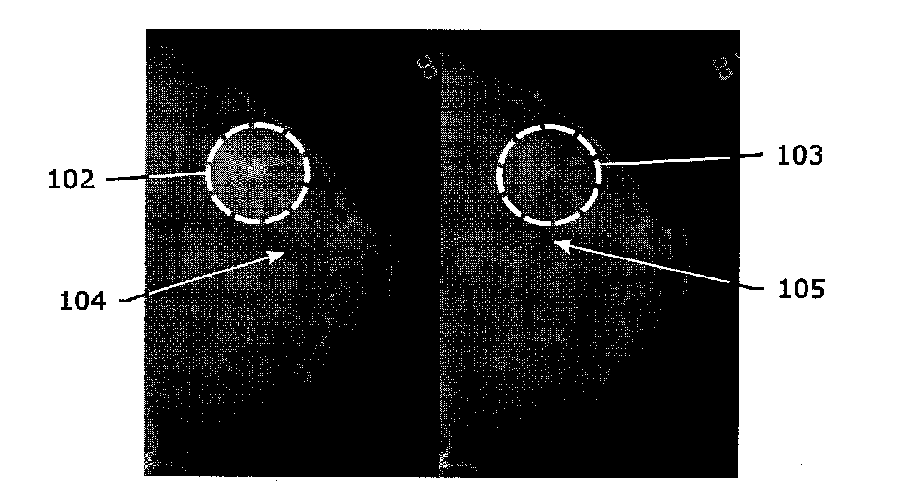
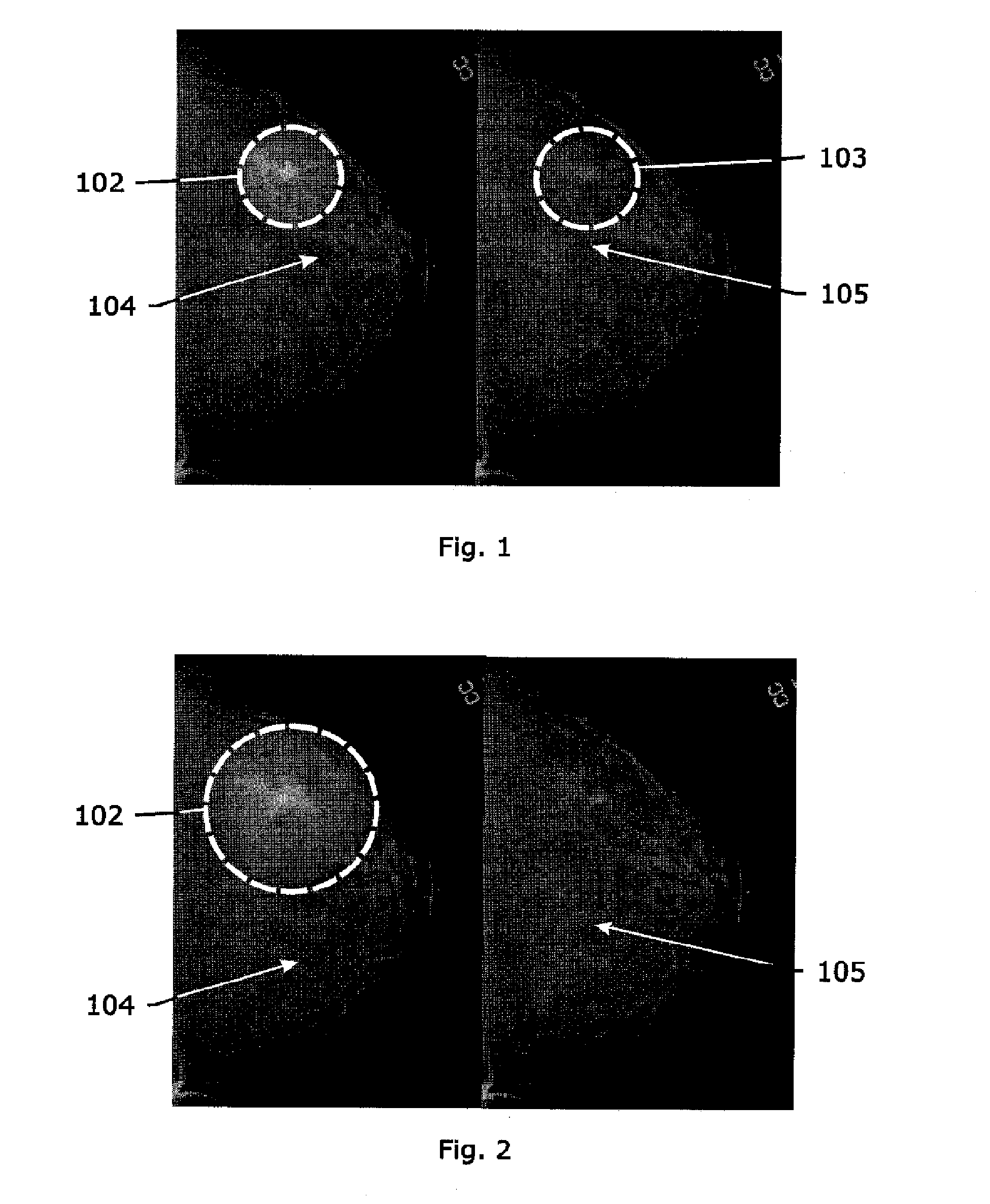
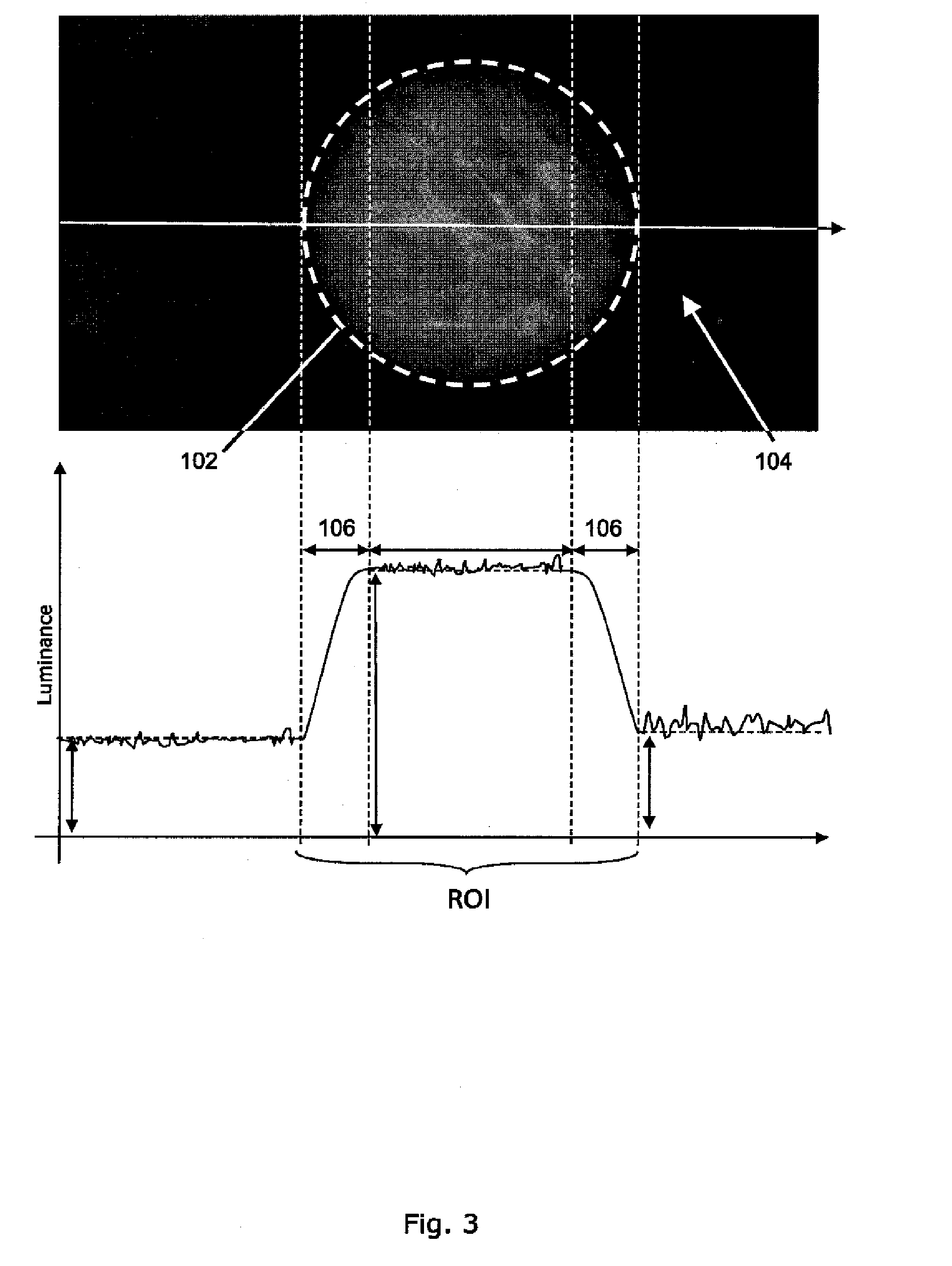
[0078]The present invention relates to a system and method providing the viewer with an increased ability to perceive subtleties in a ROI in an image on a display.

[0079]As used herein, the term “display” is intended to refer to any type of display. The term “display” should not be limited to any particular type of display, and includes such things as cathode ray tube devices, transmissive displays, emissive displays, projectors, and any other type of apparatus or device that is capable of displaying an image for viewing.

[0080]As used herein, the term “n-layer display” refers to a multilayer display where “n” represents the number of layers of the display including the layer driven in accordance with the image table. For example, a typical LCD display could be considered a 2 layer display having a backlight layer and an LCD panel layer. One of the display layers may either emit light with a specific 2D spatial profile that can be altered (e.g., an emissive layer), or spatially modula...


PUM


Abstract

A system and method provide enhanced perceived contrast within a region of interest (102) of an image being displayed in order to enable viewers to more easily perceive subtle features in images, such as during medical diagnostics. The enhanced perceived contrast may be implemented using software only, hardware only, or a combination of hardware and software. If the backlight of a display includes only one or few light sources, the enhanced perceived contrast can be achieved through a software only solution in which the area (104) outside of the ROI (102) is darkened. If the backlight of the display comprises, for example, an LED matrix, enhanced perceived contrast may be implemented through a hardware only solution in which the luminance of the display is increased in the ROI (102). In addition, enhanced perceived contrast may also be achieved through a solution utilizing both hardware and software.

Description

FIELD OF THE INVENTION[0001]The present invention relates generally to image display devices, and particularly to methods and systems for adjusting display parameters of image display devices.BACKGROUND[0002]When using imaging devices for diagnostic purposes, clinicians often are looking for very subtle image features that can indicate the presence of disease. It is well known that brighter displays provide clinicians with the ability to see more subtle features as compared to darker displays having the same physical contrast. It is for this reason that medical displays in particular are typically designed to be as bright as possible with the best achievable contrast.[0003]Typical medical displays are either transmissive or emissive. Transmissive displays, such as Liquid Crystal Displays (LCDs), utilize a backlight with one or more light sources, such as Cold Cathode Fluorescent Lamps (CCFLs), Light Emitting Diodes (LEDs) and the like, and a dedicated optical component, such as a li...

Claims


Application Information

Patent Timeline
Patent Type & Authority Applications(United States)
IPC IPC(8): G06T5/00
CPCG09G5/10G09G2320/0285G09G2320/062G09G2320/0646G06T5/007G09G2320/0686G09G2340/045G09G2360/16G09G2320/066
Inventor MARCHESSOUX, CEDRIC FABRICEVETSUYPENS, ARNOUT ROBERT LEONTINE
Owner BARCO NV
Why Eureka
Try Eureka