Piezoelectric pump

a piezoelectric pump and fluid technology, applied in the direction of machines/engines, positive displacement liquid engines, mechanical equipment, etc., can solve the problems of low clamping force, low pump pressure, and fluid contact friction surfaces of the housing and the clamping section that are displaced, so as to achieve reliable, versatile, and effective piezoelectric pumps

Active Publication Date: 2013-10-31
RENK LIMITED LIABILITY
View PDF1 Cites 8 Cited by
  • Summary
  • Abstract
  • Description
  • Claims
  • Application Information

AI Technical Summary

Benefits of technology

[0007]Introducing a displacer of pumped fluid into the design, connected with the front piezoelectric

Problems solved by technology

The main drawback of the analogue is that the displaced fluid contacts friction surfaces of the housing and the clamp sections, because the front clamp section acts as the fluid displacer in this design.
It cause low clamping force and as a consequence cause low pump pressure.
Also it may cause corrosion, wear and quick pump failure when chemically aggressive

Method used


Image

  • Piezoelectric pump
  • Piezoelectric pump
  • Piezoelectric pump

Examples


Embodiment Construction

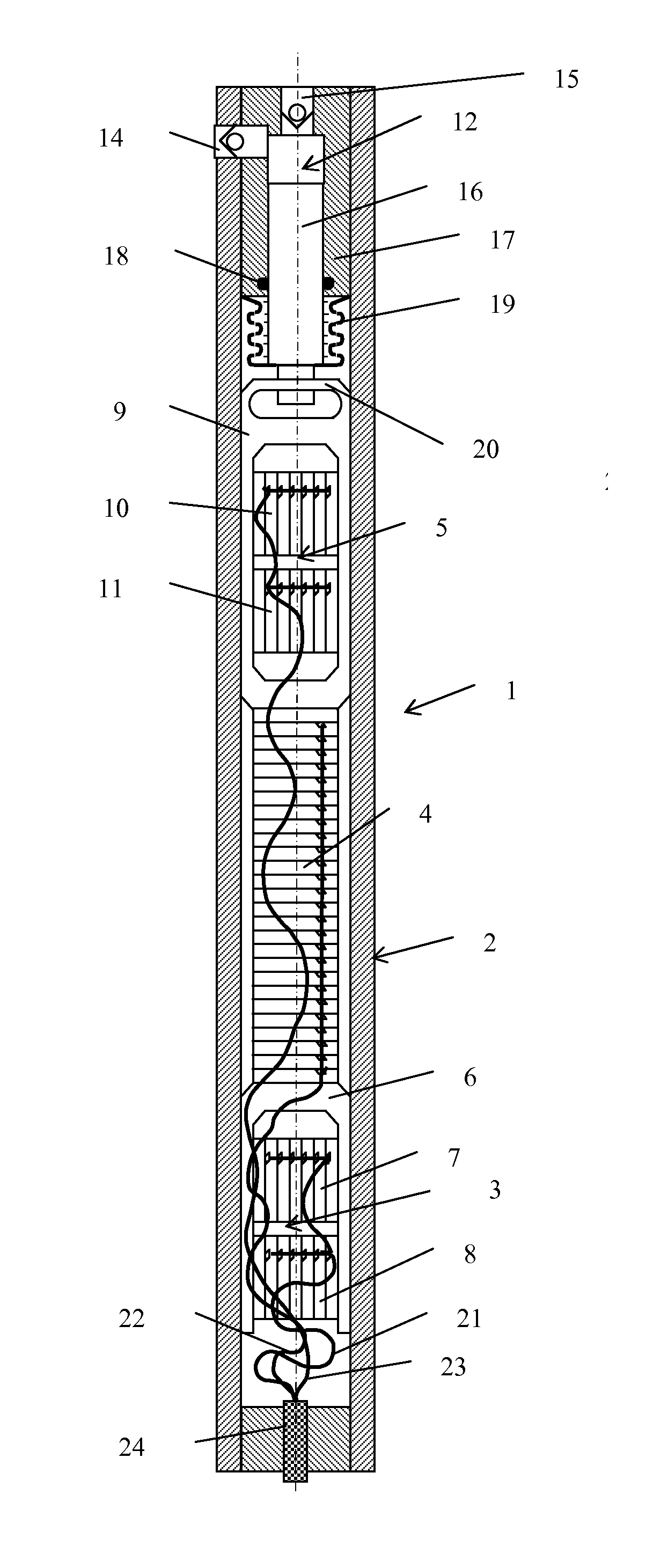
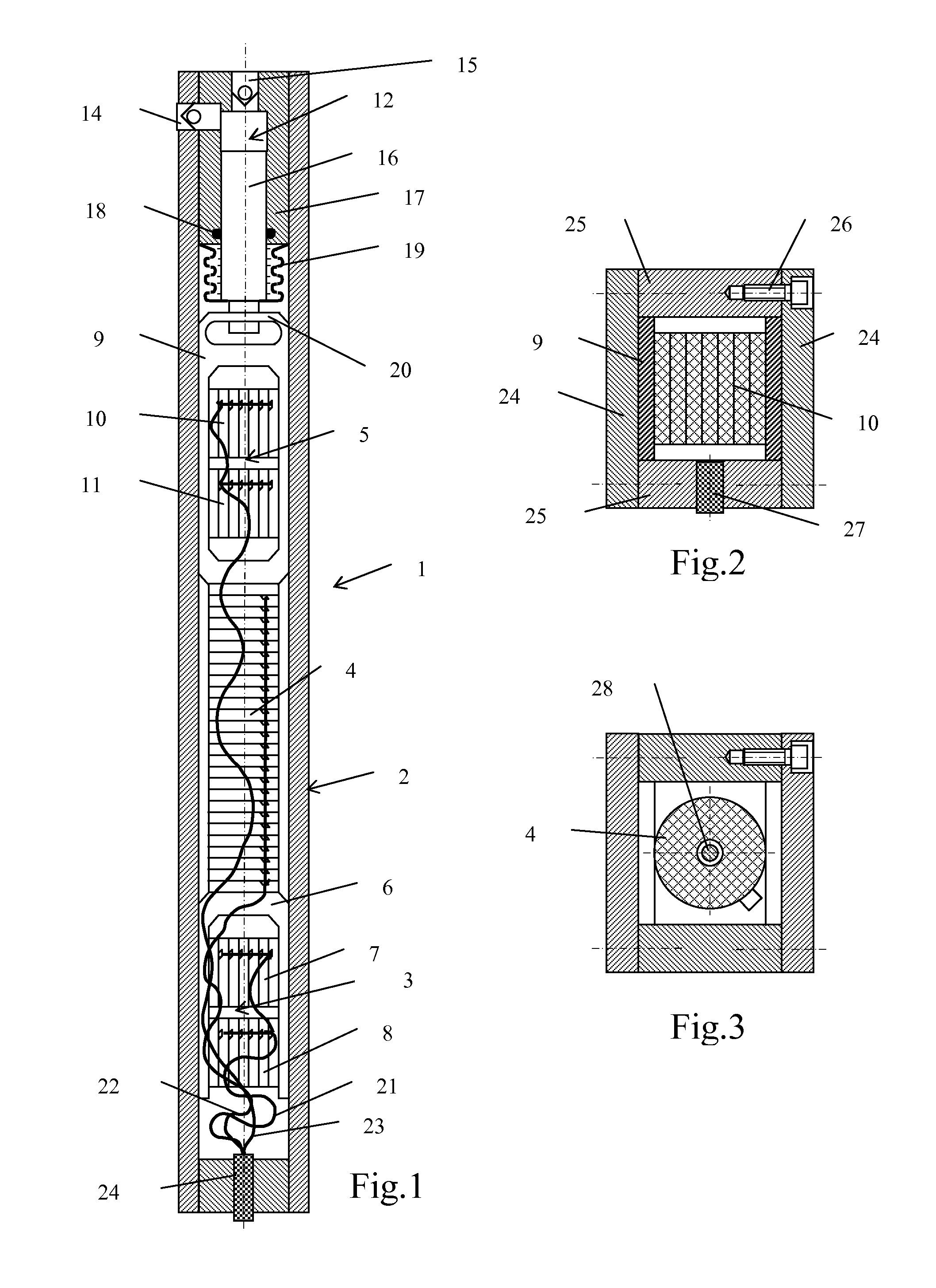
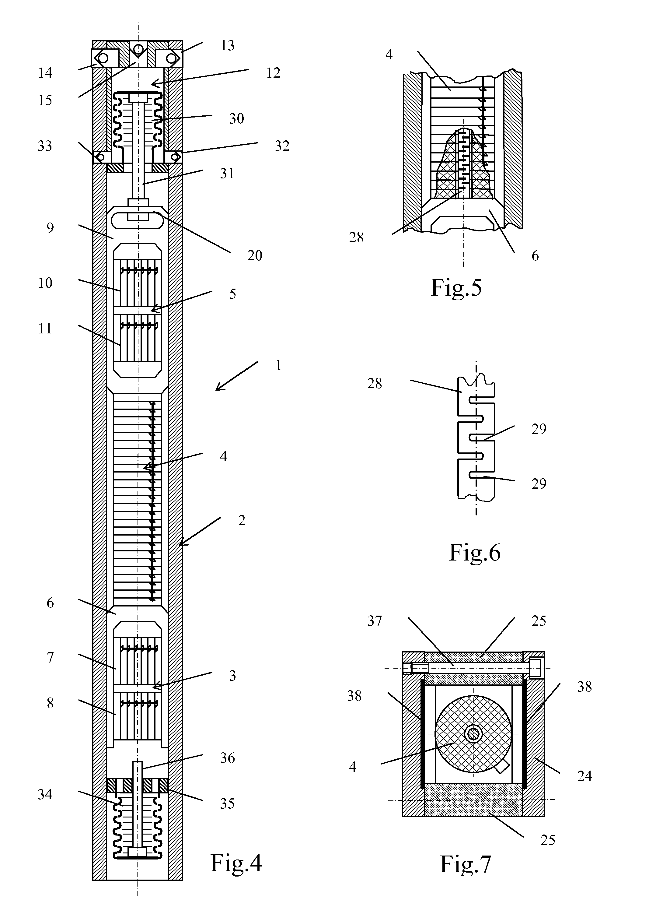
[0017]The piezoelectric pump 1 (FIG. 1 and 4) comprises a housing 2, a rear piezoelectric clamp section 3, a piezoelectric extender section 4, a front piezoelectric damp section 5. The rear piezoelectric damp section 3 consists of a bracket 6, piezostacks 7 and 8. The front piezoelectric clamp section 5 consists of a box 9 and piezostacks 10 and 11. Depending on required pressure the required number of the piezostacks in the pump clamp sections is included. There is a displacer 12 of the pumped fluid in the front part of the pump. To provide cycling operation there are inlet valves 13, 14 and an exhaust valve 15.

[0018]For the pump shown in FIG. 1, as a displacer of fluid a plunger pair 12 is selected consisting of a plunger 16 and a plunger housing 17. A seal 18 is used to prevent leakage. A bellows 19 is added to the design shown in FIG. 1, completely isolating fluid pumped by the plunger pair from the housing 1, where the piezoelectric sections 3, 4 and 5 move. The plunger 16 is c...


PUM


Abstract

The piezoelectric pump comprises a housing, containing the following components connected in series: a rear piezoelectric clamp section, a piezoelectric extender section and a front piezoelectric clamp section. A displacer of pumped fluid is connected to the front piezoelectric clamp section. Electric pulses accessing at sections from a control station cause said sections to become fixed alternately inside the housing. Under the effect of electric pulses, the piezoelectric extender section moves the displacer step-by-step in one direction. Positive effect achieved by the invention is that of increasing the service life of the piezoelectric pump, expanding the scope of use thereof by increasing the number of fluids that can be pumped and also providing for a greater pressure by preventing contact between the pumped fluid and the friction surfaces of the housing and the piezoelectric clamp sections.

Description

FIELD OF THE INVENTION[0001]The invention relates to a device for pumping fluids, and may be used in industry, transport and households when pumping liquids, and other incompressible and compressible fluids.BACKGROUND OF THE INVENTION[0002]The closest analogue of the claimed technical solution is a piezoelectric pump to displace fluid, the pump is part of the dispenser described in the U.S. Pat. Nos. 7,682,354, 23 / 03 / 2010, U.S. Class 604 / 890.1. The pump includes a housing, a rear piezoelectric clamp section, a piezoelectric extender section, a front piezoelectric clamp section, the sections are contained in the housing and connected in series. The clamp sections are mace of piezoelectric material that can press on the walls of the housing from inside at accession of an electric potential to them. The piezoelectric extender section is made of a material capable to change its length at accessing of an electric potential to it.[0003]The main drawback of the analogue is that the displac...

Claims


Application Information

Patent Timeline
IPC IPC(8): F04B17/00
CPCF04B17/003
Inventor KUZNETSOV, ANDREY LEIONIDOVICH
Owner RENK LIMITED LIABILITY
Why Eureka
Try Eureka