Battery temperature control device

a temperature control device and battery technology, applied in battery/fuel cell control arrangement, battery maintainance/servicing, primary cell maintenance/service, etc., can solve the problem of unfavorable continuous maintenance of the heater at its de-energized or deactivated (turned off) state, and achieve the effect of reducing the electric power consumption

Active Publication Date: 2013-10-31
NISSAN MOTOR CO LTD
View PDF3 Cites 36 Cited by
  • Summary
  • Abstract
  • Description
  • Claims
  • Application Information

AI Technical Summary

Benefits of technology

[0018]Hence, it is possible to avoid the battery from remaining less than the predetermined temperature, and thus it is possible to prevent the worst situation, for example, a situation such that a battery electrolyte freezes.
[0019]Additionally, only when it has been determined that the battery becomes less than the predetermined temperature at another time when the predictive time has expired, the battery can be heated by the heater, thereby ensuring the aforementioned effects. In this manner, the battery temperature control device starts up only when battery temperature control is really required, and hence it is possible to achieve the aforementioned effects with a minimum electric power consumption.

Problems solved by technology

On the other hand, even when, owing to a high outside air temperature at the time when the ignition switch has been turned OFF, the heater has not yet been energized or activated (turned ON) during initial stages of the ignition-switch turn-OFF period, and thereafter the outside air temperature has fallen, the heater is undesirably kept continuously at its de-energized or deactivated (turned OFF) state.
This leads to the problem that the inputable / outputable electric power becomes “0” at last owing to freezing of the battery electrolyte, and hence the electric vehicle, configured to run by a battery's power, falls into a power-running disabling state.

Method used


Image

  • Battery temperature control device
  • Battery temperature control device
  • Battery temperature control device

Examples


Embodiment Construction

[0026]The embodiment made according to the invention is hereinafter described in detail with reference to the drawings.

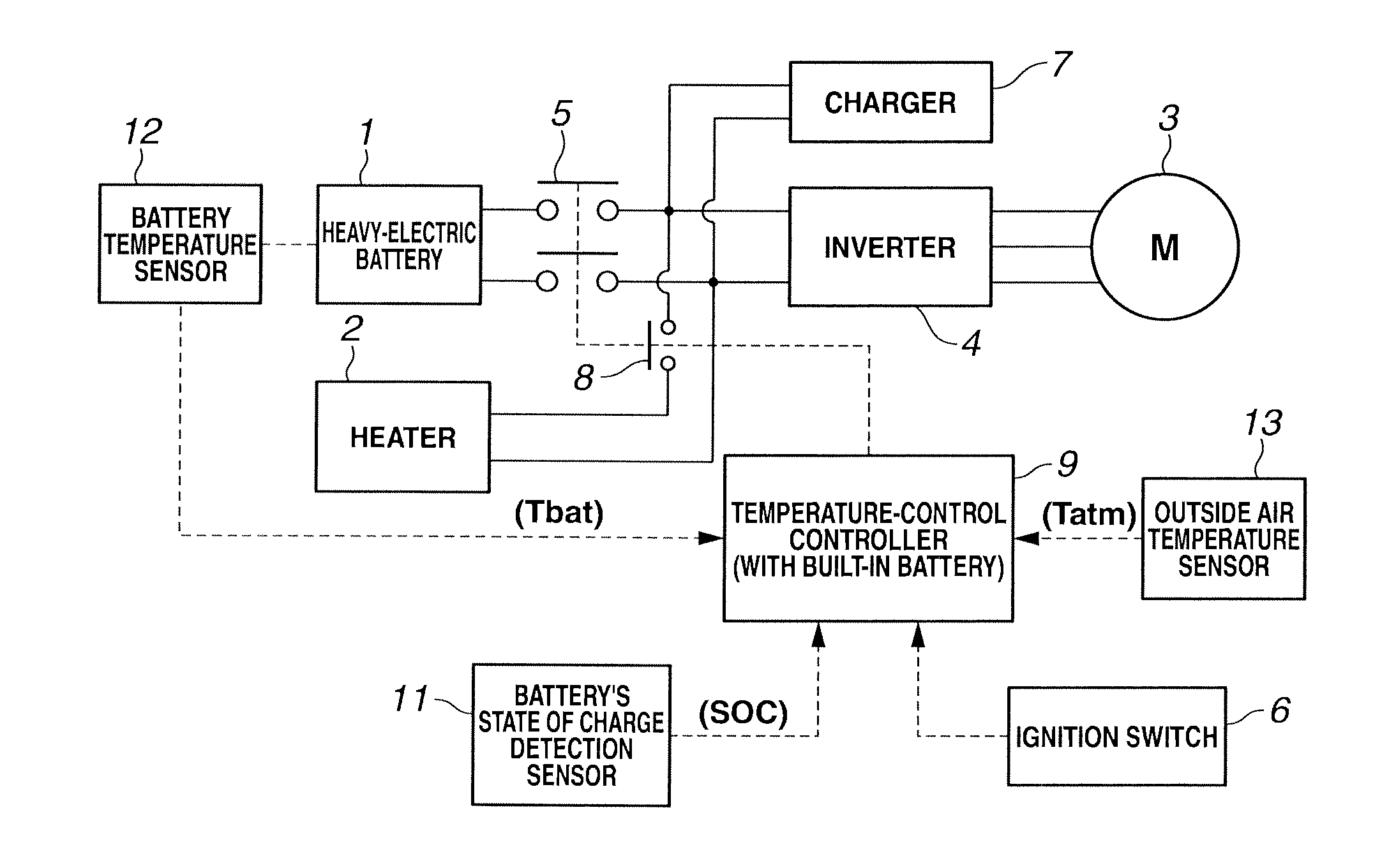
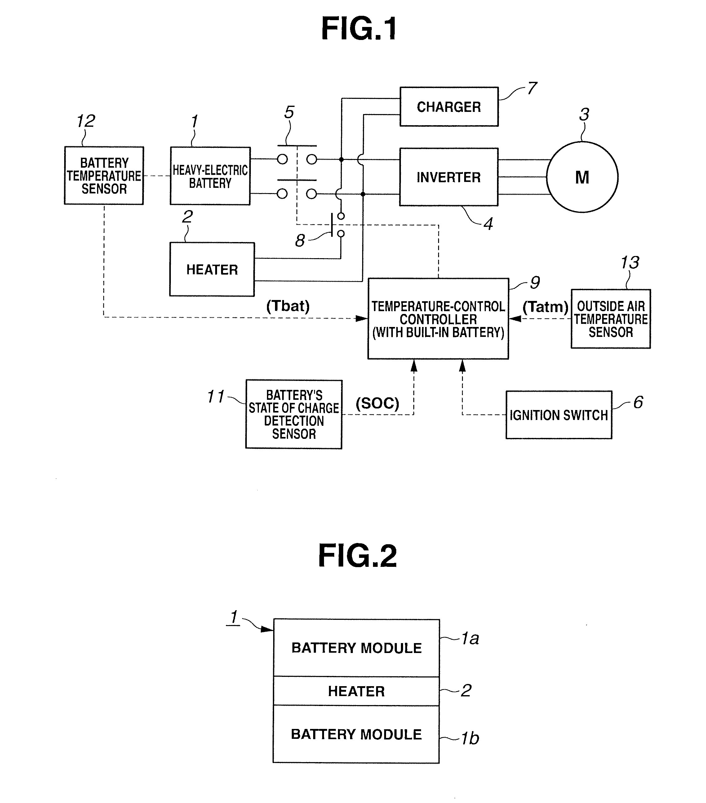
[0027]FIG. 1 is the control system diagram of the battery temperature control device of the embodiment made according to the invention. In the shown embodiment, the battery temperature control device is configured to temperature-control a heavy-electric battery 1 for an electrically-driven vehicle such as an electric vehicle, a hybrid vehicle, and the like. As shown in FIG. 2, the heavy-electric battery 1 is formed as a large-capacity battery suited to drive an electric motor and produced by unifying a plurality of battery modules 1a, 1b (two modules in FIG. 2), each of which is constructed as a unit by laminating a plurality of battery cells, into one set.

[0028]A component, denoted by reference sign“2” in FIG. 1 is a heater for temperature-controlling the battery 1. As shown in FIG. 2, heater 2 is laid out along a direction of laminating of the battery cells and lo...


PUM

PropertyMeasurementUnit
temperaturesaaaaaaaaaa
temperatureaaaaaaaaaa

Abstract

Provided is a battery temperature control device configured to automatically heat a battery with a battery-driven heater so that the battery does not freeze at a minimum electric power consumption when the battery is out of use. The battery temperature control device predicts, based on a combination of a battery temperature and an outside air temperature, a predictive time that the battery temperature is likely to be less than a first set temperature, while the battery temperature is higher than or equal to the first set temperature at which there is no risk of freezing, and sets the predictive time as the next controller startup time, and determines whether or not the battery temperature has fallen to below the first set temperature with a control program wakeup when the predictive time has expired, and battery-drives the heater when the battery temperature fall has occurred, to heat the battery.

Description

TECHNICAL FIELD[0001]The present invention relates to a battery temperature control device configured to prevent a temperature fall in a battery used in cold districts, in particular when the battery is out of use.BACKGROUND ART[0002]In the case of a battery for use in cold districts, such as a battery mounted on an electric vehicle, there is a risk that a battery electrolyte freezes when the battery is out of use.[0003]A temperature fall in the battery does not lead to a fall in a battery's state of charge SOC. However, owing to the increased internal resistance, the inputable / outputable electric power tends to fall. When a battery electrolyte has frozen, the inputable / outputable electric power becomes “0” at last, and hence an electric vehicle that a battery is an energy source for vehicle running, falls into a power-running disabling state.[0004]Therefore, it is necessary to provide a battery temperature control device configured to temperature-control by heating the battery by u...

Claims


Application Information

Patent Timeline
Patent Type & Authority Applications(United States)
IPC IPC(8): H01M6/50H01M10/50B60W10/26H01M10/60B60W20/00H01M10/48H01M10/615H01M10/633H01M10/635H01M10/6571
CPCH01M6/5038H01M10/5006H01M10/486H01M2220/20B60L2260/56B60L1/02B60L2210/30B60L2240/545B60L2240/547B60L2240/549B60L2240/662B60L2240/80Y02T90/16Y02T90/14H01M10/625H01M10/615H01M10/633Y02T10/7072B60L53/14B60L50/51B60L58/12B60L58/27Y02T10/70Y02T10/72Y02E60/10Y02T10/84Y02T90/12
Inventor KINOSHITA, TAKUYATAKANO, ATSUSHIIIMORI, TAKASHIOKINO, KAZUHIKONIIOKA, HISASHIYAMAMOTO, NAOKI
Owner NISSAN MOTOR CO LTD
Why Eureka
Try Eureka