
Grid Optimization Resource Dispatch Scheduling

a technology of grid resource and dispatch scheduling, applied in the direction of adaptive control, static/dynamic balance measurement, instruments, etc., can solve the problems of inefficient means to ensure power can be delivered in response, rapid increase of electrical load of the power grid, damage to the environment, etc., to optimize the overall grid utilization, optimize the effect of resource availability and improved grid efficiency

Inactive Publication Date: 2013-10-31
INNOVARI
View PDF1 Cites 14 Cited by
  • Summary
  • Abstract
  • Description
  • Claims
  • Application Information

AI Technical Summary

Benefits of technology

The patent describes a system for managing the use of resources to control electrical loads on a utility grid. The system receives requests from utilities or other parties to change the amount of electrical load they need over a specific period of time. The system uses data to determine the available capacity of resources and scheduling instructions for each resource to meet the desired change in load. The system can also consider factors like weather and load demand to optimize the use of resources. The patent also describes the process of controlling consumption to balance new intermittent renewable resources, improve grid efficiency, and enable cost-effective decisions. Overall, the system helps to optimize the use of resources on the grid and improve its overall efficiency.

Problems solved by technology

For example, on a hot day, millions of consumers turning on their heating, ventilation and air conditioning (HVAC) units would cause a rapid increase in the electrical load of the power grid.
Operating in standby mode allows a generator to deliver power quickly, improving the reliability of the grid, but is costly, damaging to the environment, and an inefficient means to assure power can be delivered in response to consumption demands.
Wind and solar generation resources only provide power to the grid when the wind is blowing or the sun is shining, so the challenge of matching supply and demand has grown in complexity and has forced many more fossil fueled power plants to be built and operated in standby mode to deal with these rapid and significant fluctuations.

Method used


Image

  • Grid Optimization Resource Dispatch Scheduling
  • Grid Optimization Resource Dispatch Scheduling
  • Grid Optimization Resource Dispatch Scheduling

Examples


Embodiment Construction

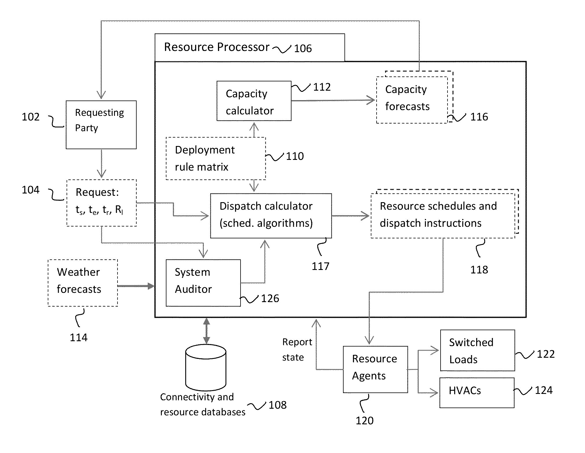
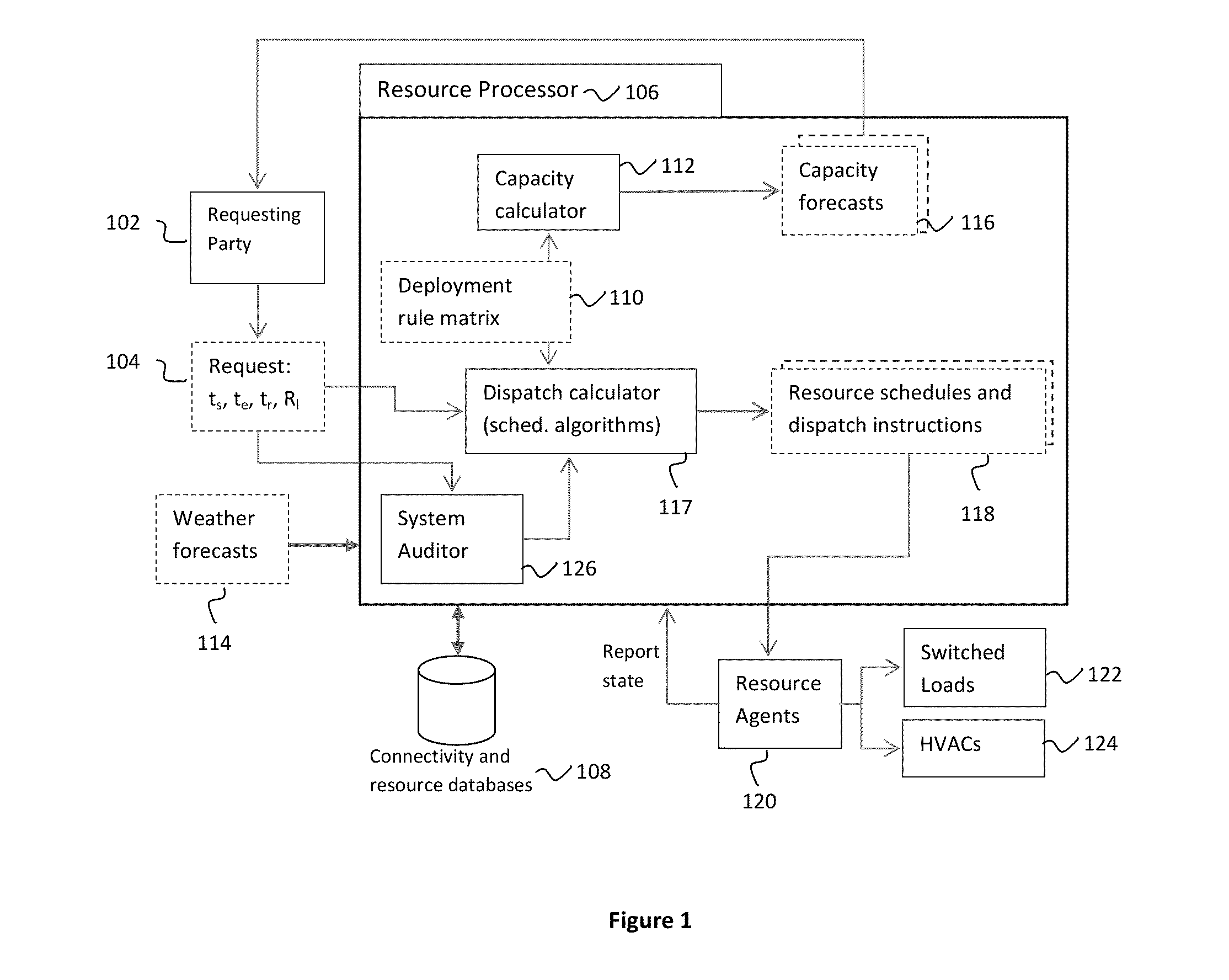
[0029]FIG. 1 is a schematic overview 100 of the components contributing to the process of scheduling resources to satisfy a request. A request generator such as a utility or other entity 102 knowing the total aggregated resource load it has under control as a function of time and temperature, issues a request 104, which may include the intent to shed a desired load from the electrical grid at a given time and duration. The request enters the resource processor 106 where algorithms generate unique schedules and instructions to control from one to many resources as may be needed to satisfy the request, and are available and under management of the entire system. The resource processor may also have electrical connectivity, normal operating characteristics of the resources and other inputs or databases 108 to determine applicable resources by geographic location, type and distribution network connection, which may be required to fulfill the request. Furthermore, the resource processor ...


PUM


Abstract

Data comprising a request specifying a desired change in electrical load for a defined period of time is received. The electrical load is associated with a plurality of resources under control of resource agents and on a utility grid. Available capacity of resources within the control of each resource agent over the defined period of time is determined. Each available capacity is determined at least using a resource load model. Using the determined available capacity of resources over the defined period of time, resource scheduling instructions are calculated for a subset of resources. The resource scheduling instructions satisfy the desired change in electrical load of the request. Data characterizing the resource scheduling instructions is provided. Related systems, apparatus, methods, and articles are also described.

Description

RELATED APPLICATIONS[0001]This application claims priority to U.S. Provisional Application No. 61 / 640,318, filed on Apr. 30, 2012, the entire contents of which are hereby incorporated by reference.TECHNICAL FIELD[0002]The subject matter described herein relates to electrical grid resource management, including the consumption of, and its relationship to, the generation of power. Specifically scheduling algorithms, electrical load modeling, forecasting of consumption, resource organization, and interfacing with a requesting party such as a utility, market participant or others for enabling grid optimization and other services.BACKGROUND[0003]The total load connected to a power grid can vary significantly over time. The total load is the sum of individual choices by many consumers at any instant in time. The result is dynamic and sometimes rapidly varying load consumption pattern which must be served by resource management of the electrical grid. For example, on a hot day, millions of...

Claims


Application Information

Patent Timeline
Patent Type & Authority Applications(United States)
IPC IPC(8): G05B13/02
CPCG05B13/02G06Q10/04G06Q10/0631G06Q50/06H02J3/04H02J3/003Y04S10/50
Inventor FRIEDRICH, LORANPIERCE, ERICHILL, JASONTILLETT, JAMESWALDEN, DAVERAYMOND, LAURAHICKMAN, CHRISDO, PHONG
Owner INNOVARI
Learn More