Air Conditioning Device for Vehicle

a vehicle and air conditioning technology, applied in domestic cooling devices, program control, instruments, etc., can solve the problems of difficult to obtain the exhaust heat that can heat the air to be supplied to the interior of the vehicle by using the electric motor, the above-mentioned vehicle air conditioning apparatus is not applicable to electric cars, and the outdoor heat exchanger is likely to be frosty, so as to reduce the electric power consumption, the effect of extending the mileage of the vehicle and minimal operation

Active Publication Date: 2013-11-07
SANDEN CORP
View PDF19 Cites 52 Cited by
  • Summary
  • Abstract
  • Description
  • Claims
  • Application Information

AI Technical Summary

Benefits of technology

[0023]According to the present invention, the quantity of heat required for a heating operation can be obtained with the minimum power consumption, and therefore it is possible to reduce the electric power consumed by the heating operation or heating and dehumidifying operation. As a result, it is possible to extend the mileage of the vehicle.
[0024]In addition, according to the present invention, only an insufficient quantity of heat release in the heat medium heating radiator is compensated by operating the heat medium heater. By this means, it is possible to minimally operate the heat medium heater to reduce the power consumption for driving the vehicle. As a result, it is possible to prevent the mileage of the vehicle from dropping.
[0025]Moreover, according to the present invention, when the battery power becomes insufficient while the vehicle is running, it is possible to effectively use the battery power in order to drive the vehicle. Therefore, it is possible to extend the mileage of the vehicle.

Problems solved by technology

Generally, an electric car uses an electric motor as a power source, and it is difficult to acquire the exhaust heat that can heat the air to be supplied to the vehicle interior by using the electric motor without an engine.
Therefore, the above-mentioned vehicle air conditioning apparatus is not applicable to electric cars.
With the vehicle air conditioning apparatus, if the heating operation is performed while the outdoor air temperature is low, the evaporating temperature of the refrigerant drops in the outdoor heat exchanger, so that a frost is likely to be formed on the outdoor heat exchanger.
If a frost is formed on the outdoor heat exchanger, the outdoor heat exchanger cannot acquire required quantity of heat.
This causes a decrease in the performance of the heating operation.

Method used


Image

  • Air Conditioning Device for Vehicle
  • Air Conditioning Device for Vehicle
  • Air Conditioning Device for Vehicle

Examples


embodiment 1

[0065]FIG. 1 to FIG. 8 show Embodiment 1 of the present invention.

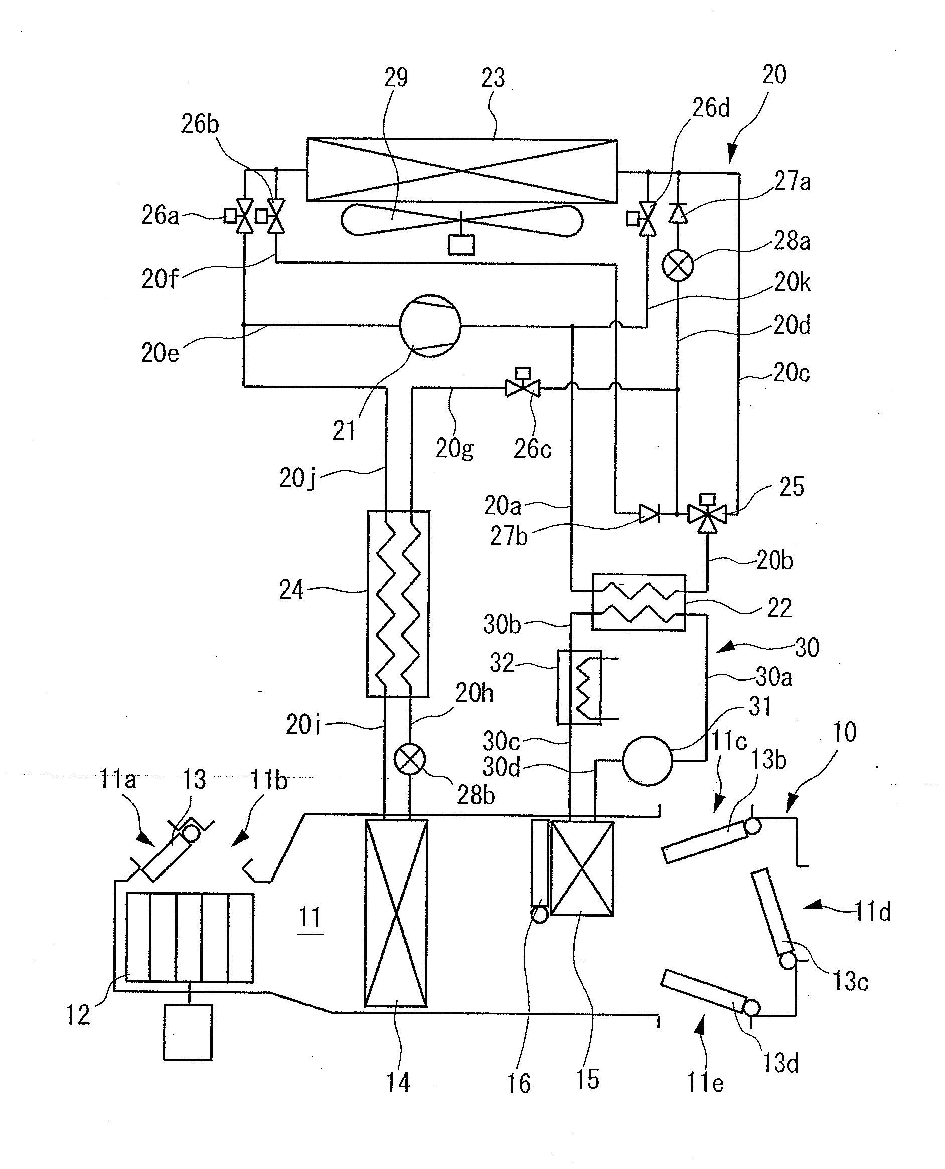
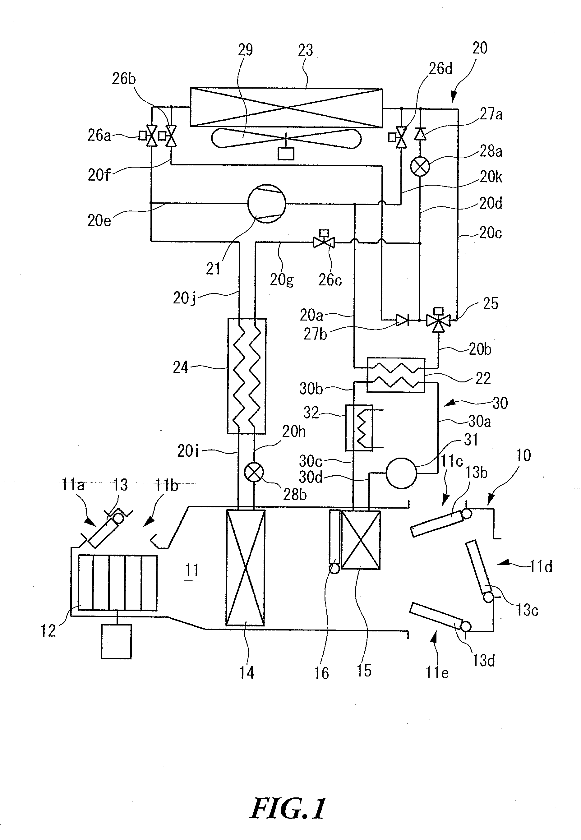
[0066]The vehicle air conditioning apparatus according to the present invention is applicable to an electric car that is run by electric power and that is driven by the electric power of a battery to be used to run the electric car. As shown in FIG. 1, this vehicle air conditioning apparatus includes an air conditioning unit 10 provided in the vehicle interior, and a refrigerant circuit 20 and a water circuit 30 that are formed across the vehicle interior and the outdoor.

[0067]The air conditioning unit 10 includes an air flow passage 11 that allows the air to be supplied to the vehicle interior to pass through. An outdoor air inlet 11a and an indoor air inlet 11b are provided in the first end side of the air flow passage 11. The outdoor air inlet 11a is configured to allow the outdoor air to flow into the air flow passage 11, and the indoor air inlet 11b is configured to allow the indoor air to flow into the air flow ...

embodiment 3

[0167]FIG. 10 to FIG. 22 show Embodiment 3 of the present invention.

[0168]As shown in FIG. 10, this vehicle air conditioning apparatus includes an air conditioning unit 10 provided in the vehicle interior, and a refrigerant circuit 20 and a water circuit 30 that are formed across the vehicle interior and the outdoor.

[0169]The air conditioning unit 10 includes an air flow passage 11 that allows the air to be supplied to the vehicle interior to pass through. An outdoor air inlet 11a and an indoor air inlet 11b are provided in the first end side of the air flow passage 11. The outdoor air inlet 11a is configured to allow the outdoor air to flow into the air flow passage 11, and the indoor air inlet 11b is configured to allow the indoor air to flow into the air flow passage 11. Meanwhile, a foot outlet 11c, a vent outlet 11d and a defroster outlet 11e are provided in the second end side of the air flow passage 11. The foot outlet 11c is configured to allow the air flowing through the ai...

embodiment 9

[0346]FIG. 28 to FIG. 35 show Embodiment 9 of the present invention.

[0347]The vehicle air conditioning apparatus according to the present invention is applicable to an electric car that is run by electric power and that is driven by the electric power of a battery to be used to run the electric car. As shown in FIG. 28, this vehicle air conditioning apparatus includes an air conditioning unit 10 provided in the vehicle interior, and a refrigerant circuit 20 and a water circuit 30 that are formed across the vehicle interior and the outdoor.

[0348]The air conditioning unit 10 includes an air flow passage 11 that allows the air to be supplied to the vehicle interior to pass through. An outdoor air inlet 11a and an indoor air inlet 11b are provided in the first end side of the air flow passage 11. The outdoor air inlet 11a is configured to allow the outdoor air to flow into the air flow passage 11, and the indoor air inlet 11b is configured to allow the indoor air to flow into the air fl...


PUM


Abstract

A vehicle air conditioning apparatus is provided that can extend the mileage of a vehicle by reducing the power consumed by the operation of a compressor and a heater. When a required quantity of heating Q_req is acquired, the minimum power sharing ratio between quantity of heat release Q_hpof a water-refrigerant heat exchanger 22 and quantity of heat release Q_htrof a water heater 32 is calculated, which allows the power consumption W_total to be minimized, and a compressor 21 and the water heater 32 is operated based on the result of the calculation.

Description

CROSS-REFERENCES TO RELATED APPLICATIONS[0001]This application claims the benefit of Japanese Patent Application No. 2011-010674, filed Jan. 21, 2011, Japanese Patent Application No. 2011-040131, filed Feb. 25, 2011, and Japanese Patent Application No. 2011-040133, filed Feb. 25, 2011, which are incorporated herein by reference.TECHNICAL FIELD[0002]The present invention relates to a vehicle air conditioning apparatus applicable to, for example, electric cars.BACKGROUND ART[0003]Conventionally, this sort of vehicle air conditioning apparatus includes: a compressor driven by an engine as a power source of a vehicle; a radiator provided outside the vehicle interior; and a heat exchanger provided inside the vehicle interior. With this vehicle air conditioning apparatus, a cooling operation is performed by: releasing the heat from the refrigerant discharged from the compressor in the radiator; absorbing the heat into the refrigerant in the heat exchanger; and supplying the air subjected ...

Claims


Application Information

Patent Timeline
Patent Type & Authority Applications(United States)
IPC IPC(8): B60H1/00
CPCB60H1/00007B60H1/00392B60H1/00428B60H1/00899B60L1/003B60L1/02B60L2240/12B60L2240/34B60L2240/36B60L2240/665B60L2240/68B60L2240/80B60L2250/12B60L2250/16B60L58/12Y02T10/70Y02T10/72Y02T10/88Y02T90/16B60H1/00764B60H1/00785B60H1/00807B60H1/00864B60H1/00885B60H1/00907B60H1/2218B60H1/2221B60H2001/325B60H2001/3261B60H2001/3272G05B19/042G05B2219/2614
Inventor MIYAKOSHI, RYOSUZUKI, KENICHITAKEI, HIDENORI
Owner SANDEN CORP
Why Eureka
Try Eureka