Fluid leakage detection system

a leakage detection and flue gas technology, applied in the direction of instruments, structural/machine measurement, gas/liquid distribution and storage, etc., can solve the problems of requiring human presence, causing false safety impressions for users, and not allowing the detection of “small” leakages, etc., to achieve the effect of short response tim

Inactive Publication Date: 2013-11-07
CLEVERGAS HLDG
View PDF9 Cites 38 Cited by
  • Summary
  • Abstract
  • Description
  • Claims
  • Application Information

AI Technical Summary

Benefits of technology

[0016]One aim of the invention is to procure, for a domestic fluid distribution installation, an automatic system for detecting fluid leakage suitable for detecting, at any time, any type of fluid leakage reliably and to react with a short response time.

Problems solved by technology

The first have the drawback of requiring a human presence.
The second are disadvantageous since they may be situated remote from the leak and therefore react late, or even never react, which gives the user a false impression of safety.
These systems do not however permit the detection of “small” leaks since the corresponding flow meters do not have the necessary sensitivity.
For the same reason, these systems are also not able to detect “small” leaks.
The periods of absence of consumption are predetermined and are obtained either during the night, or by cutting off all the consuming equipment, which is detrimental to the comfort of the user.
This system therefore does not provide any means for determining the random absence of consumption, which is detrimental to the safety of the installation and thus to the efficiency of the detection system.

Method used


Image

  • Fluid leakage detection system
  • Fluid leakage detection system
  • Fluid leakage detection system

Examples


Embodiment Construction

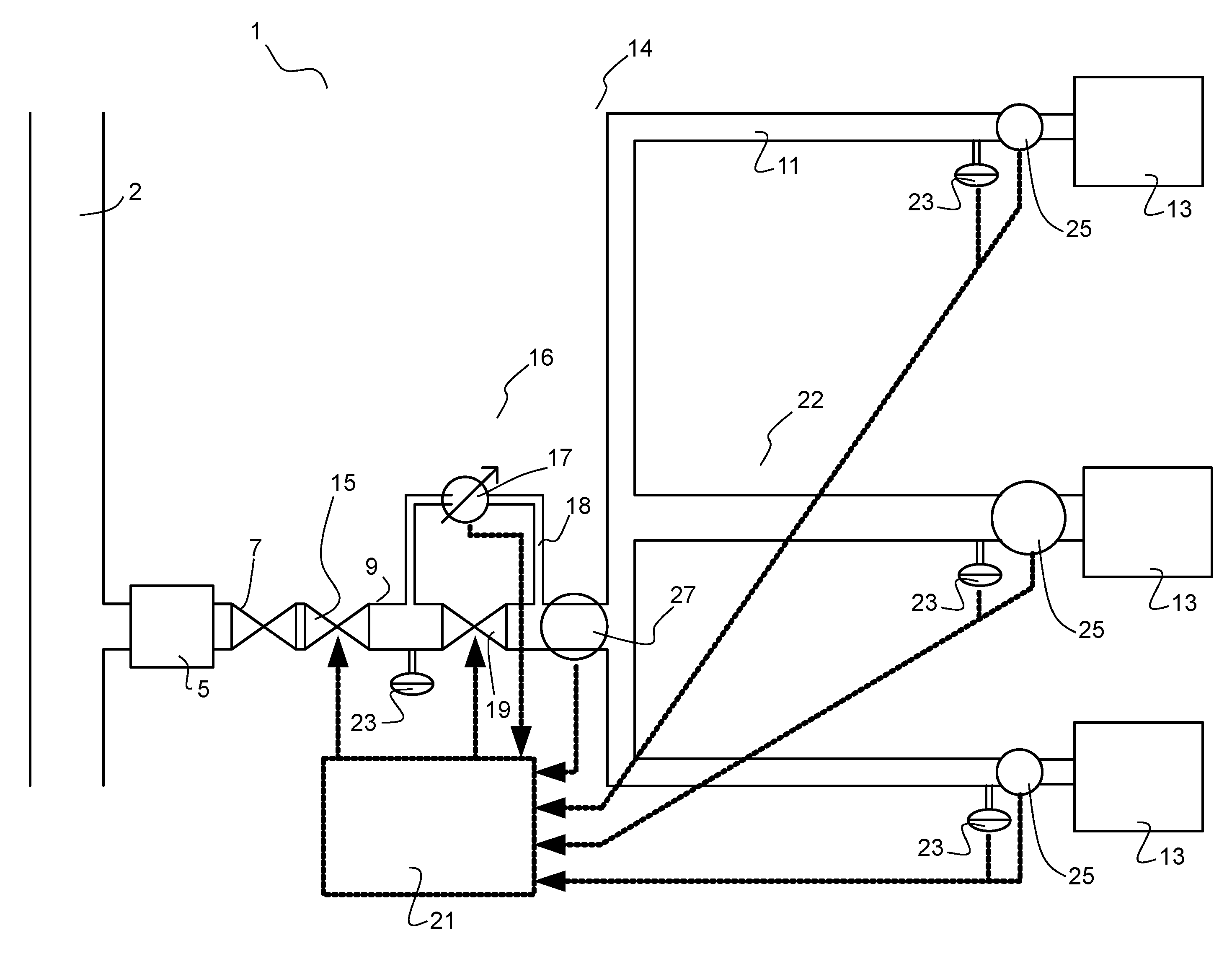
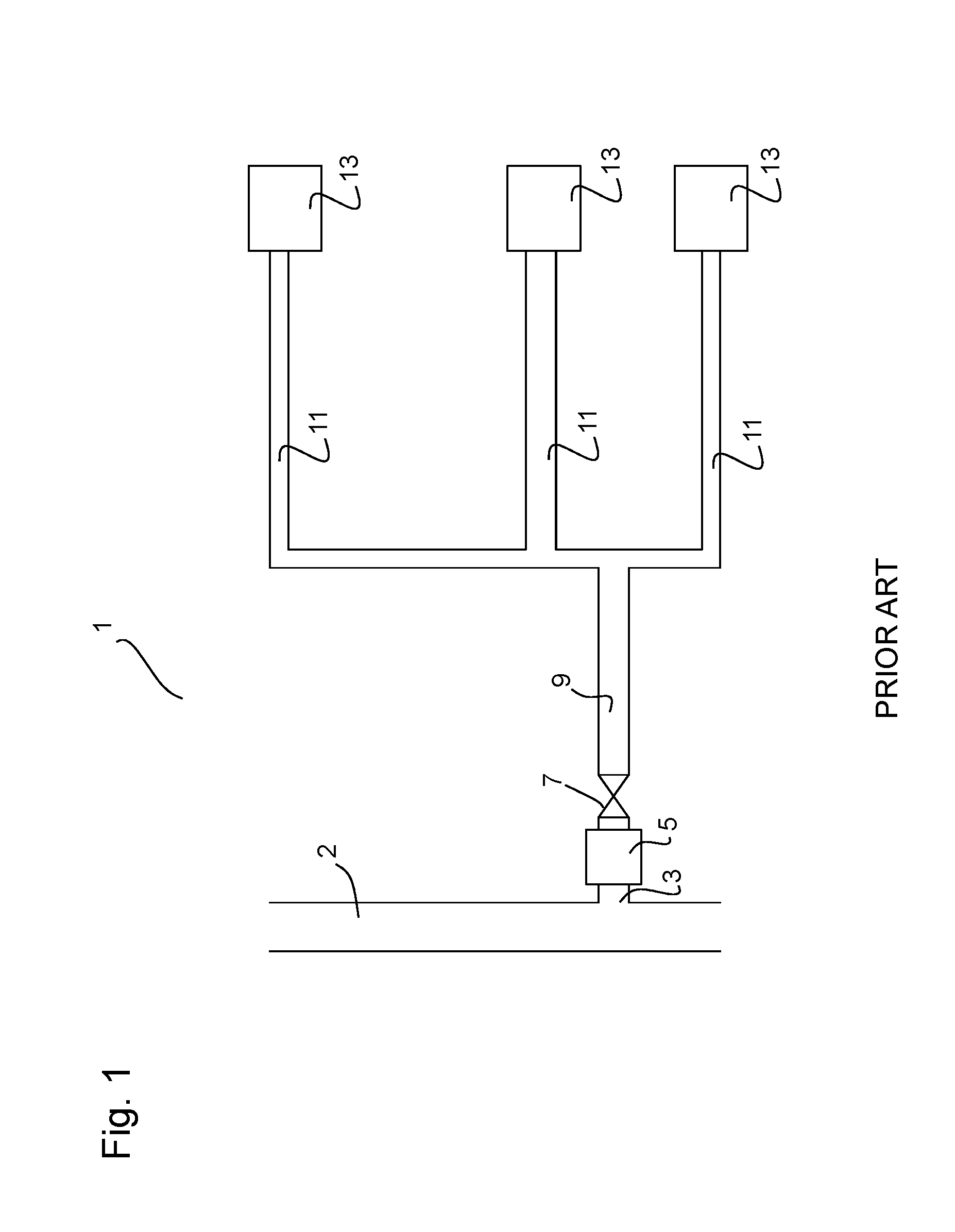
[0033]FIG. 1 shows a typical combustible gas distribution installation 1. The gas is brought by a public pipe 2 to a domestic branch 3. A meter 5 meters the consumption at the start of the domestic branch 3. This meter is followed by a manual main valve 7 controlling the opening the domestic installation 1. A domestic distribution system comprises a main pipe 9 emerging on a plurality of secondary pipes 11 intended each to supply an item of consuming equipment 13.

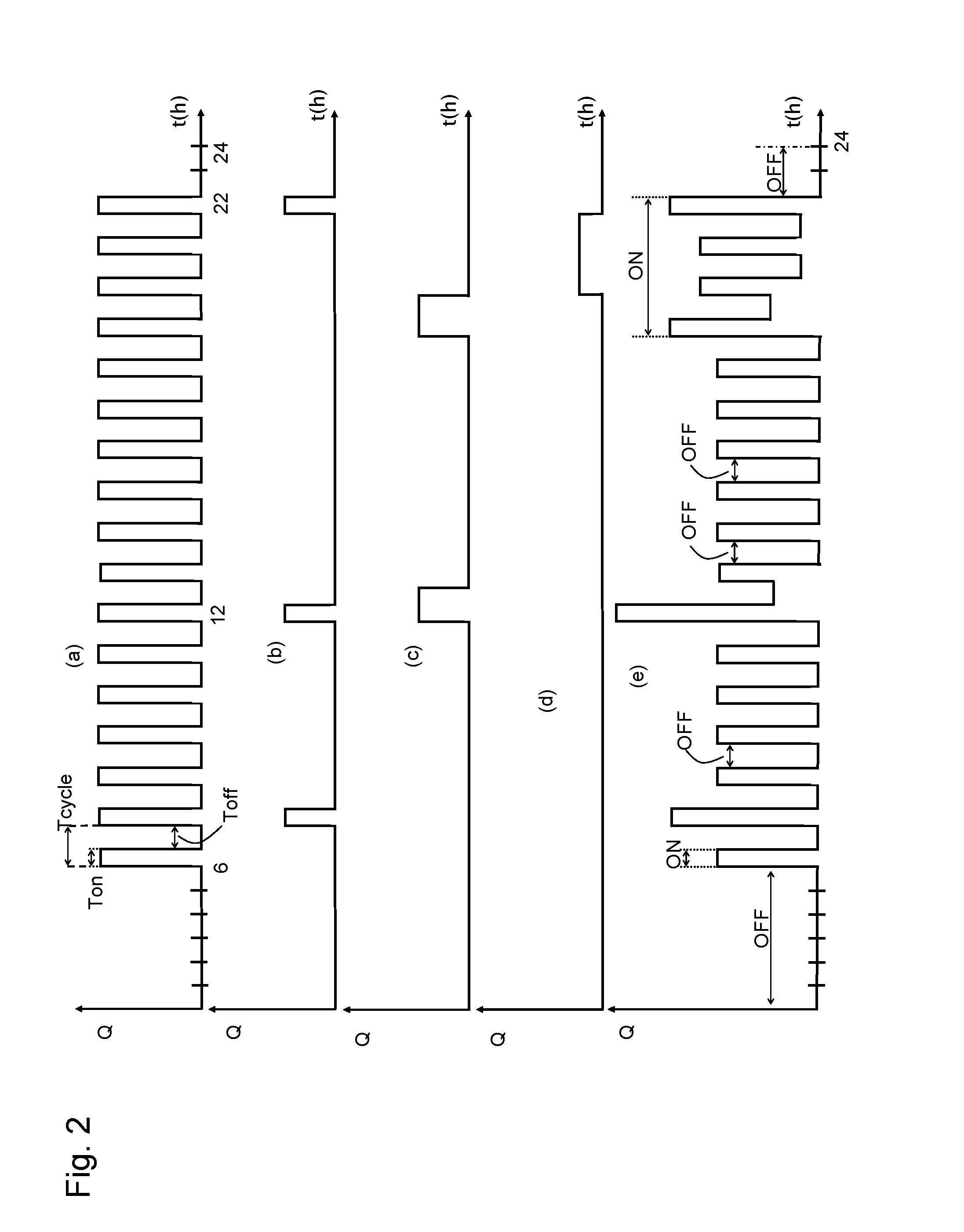
[0034]Each item of consuming equipment 13 obviously does not function continuously but has an operating cycle Tcycle such that Tcycle=Ton+Toff, Ton and Toff signifying respectively a period of functioning and a period of non-functioning of the equipment 13. This cycle is generally appreciably less than 24 hours and varies in particular according to the external temperature. Each cycle is independent of the others since there is no correlation between them.

[0035]In addition, it is possible to obtain several periods during a ...


PUM


Abstract

Fluid-leakage detection system (14) for a domestic fluid distribution installation (1), comprising: a main fluid feed pipe (9) connected to at least one item of fluid consuming equipment (13) through a corresponding secondary pipe (11), a cutoff valve (15) for cutting off the main feed pipe (9) in the event of the detection of any leak, a small-leak detection device (16) activated in the case of zero global consumption, a flow meter (25) on the secondary pipe of each item of consuming equipment (13) for establishing the state of the global consumption.

Description

FIELD OF THE INVENTION[0001]The invention relates to a fluid leakage detection system for a domestic fluid distribution installation.INTRODUCTION[0002]Detecting fluid leaks as soon as possible makes it possible to limit the human, material and financial losses that may result therefrom to the maximum possible extent.[0003]This problem is particularly sensitive in the case of combustible gas, the accumulation of which in a closed space increases the risk of explosion. In order to reassure domestic consumers, gas distribution companies seek to equip domestic installations with gas leakage detection systems that are at the same time simple, economical, reliable, rapid and efficacious, which moreover stimulates the consumption of gas in the population and makes their equipment more profitable.PRIOR ART[0004]Various fluid leakage detection systems are known in the prior art.[0005]In the field of gas detection for example, there exists portable or fixed “sniffer” analysing apparatus. The ...

Claims


Application Information

Patent Timeline
Patent Type & Authority Applications(United States)
IPC IPC(8): G01M3/28
CPCG01M3/28F17D5/02G01M3/2807F17D1/20F17D3/18F17D5/005F17D5/06Y10T137/7761Y10T137/2562Y10T137/87877Y10T137/86734
Inventor BOURGEOIS, PIERRE
Owner CLEVERGAS HLDG
Why Eureka
Try Eureka