System and method for monitoring strain & pressure

a technology of strain and pressure measurement and monitoring system, which is applied in the field of system and method for measuring strain and/or pressure in underground formations, can solve the problems of inability to measure in-situ, inconvenient calibration, and fracture of rock matrix,

Inactive Publication Date: 2013-11-14
SHELL OIL CO
View PDF6 Cites 79 Cited by
  • Summary
  • Abstract
  • Description
  • Claims
  • Application Information

AI Technical Summary

Benefits of technology

[0010]The change in strain detected in step d) can be used as an indication that the effect of the well treatment has extended to or beyond the limit of a predetermined preferred treatment zone and the well treatment may be controlled or ceased based on the determinations made in step e). The present method can also be used to determine information about the formation between the first well and the monitoring well.

Problems solved by technology

These operations generally create high pressures in the formation, often leading to breakdown (fracturing) of the rock matrix, and will strain the formation in a volume surrounding the intervention.
Notwithstanding the foregoing, there is currently no in-situ method for measuring, in a volume around the treatment well and at an acceptable cost and accuracy, formation strain during well interventions.
Surface and vertical seismic profile (VSP) measurements can be used, but these are not accurate and require calibration, as they yield formation velocity as the raw measurement, which in turn needs to be converted into strain.
In principle, formation strainmeters could be deployed in a permanent installation outside of casing but this can be prohibitively expensive, especially if multiple wells and depth stations are targeted.
Furthermore, it is sometimes desirable to detect formation strain and / or pressure in a treatment well, which is difficult if not impossible using traditional pressure or strain gauges.

Method used


Image

  • System and method for monitoring strain & pressure
  • System and method for monitoring strain & pressure

Examples


example 1

Hydraulic Fracturing

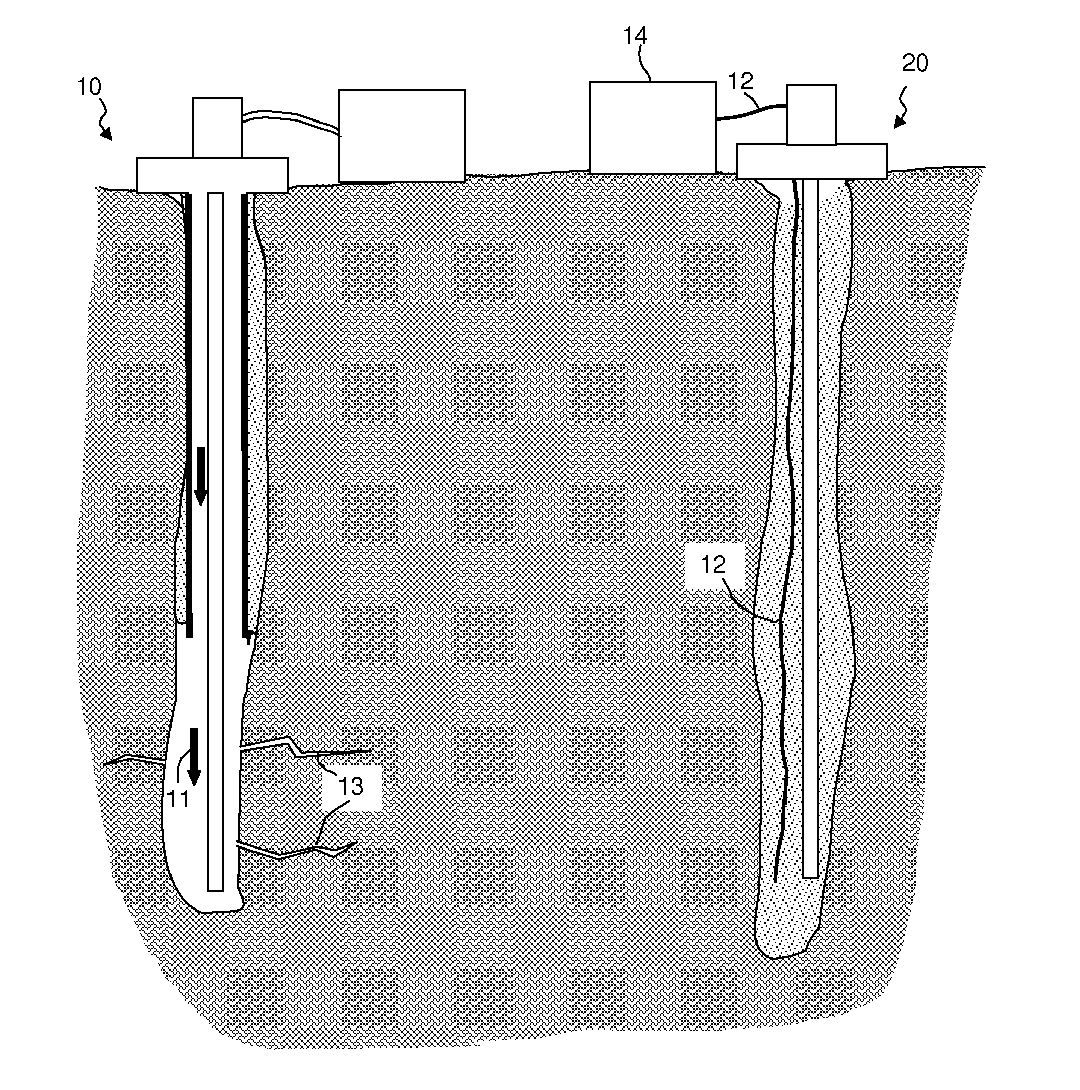
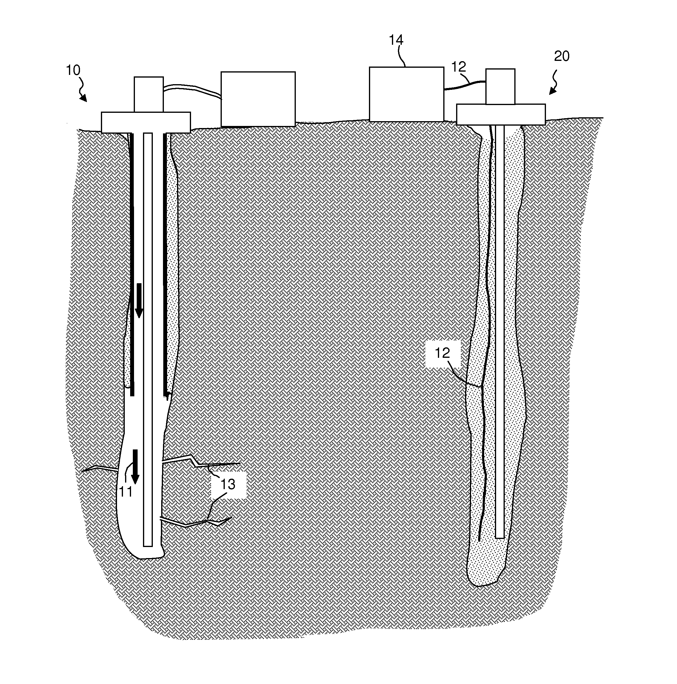
[0029]According to a first exemplary embodiment, distributed OTDR sensing can be used to detect hydraulic fracturing according to the following workflow:[0030]deploy one or more DAS fibers in one or more wells in the vicinity of an intended hydraulic fracturing operation;[0031]prior to hydraulic fracturing in the area, record noise levels along the fiber as a control measurement;[0032]upon initiation of pumping of fracture fluids, for any or all fracture stages and fluid types, including mini-frac (or test frac), record the strain field as measured by the DAS system, for all locations in the well where the formation can be affected by the fracture operation;[0033]simulate the strain field as a function of time and space using a geomechanical simulation;[0034]from the results of the simulation, make a prediction of the axial strain measurements at the places where the DAS fibers have made the measurements;[0035]compare the predictions and measurements and adjust t...

example 2

Depletion

[0040]According to a second exemplary embodiment, the inventive methods are used to measure time-dependent strain in a depleting field. More specifically, the inventive methods provide a way to measure moderate resolution differential depletion in a reservoir. The cost and availability of fiber optic sensors, allows construction of an areal picture of depletion induced strain.

[0041]Thus, according to this embodiment, distributed OTDR sensing can be used to detect and monitor field depletion according to the following workflow:[0042]deploy one or more DAS fibers in one or more wells in the vicinity of an intended hydraulic fracturing operation;[0043]prior to field startup, record noise levels along the fibers as a control measurement;[0044]upon initiation of field depletion, the strain field as measured by the DAS system, for all instrumented wells;[0045]simulate the strain field as a function of time and space using a geomechanical simulation;[0046]from the results of the s...


PUM


Abstract

A method for monitoring a well treatment, comprising the steps of installing at least one distributed acoustic strain sensor in at least one monitoring well, said monitoring well being a known distance from the treatment well, initiating a well treatment on the first well, monitoring the formation surrounding the monitoring well using the distributed acoustic strain sensor, and using the distributed acoustic strain sensor, detecting a change in strain at a first location in the monitoring well, using the change in strain to make determinations about the well treatment. The sensor may comprise a fiber optic cable. The change in strain may be used as an indicator that the effect of the well treatment has extended beyond a predetermined preferred treatment zone, the treatment may be a fracture treatment, and the well treatment may be controlled or ceased based on the determinations made in step e).

Description

RELATED APPLICATIONS[0001]The present case claims priority to U.S. provisional application Ser. No. 61 / 425,603, filed on 21 Dec. 2010, which is incorporated herein by reference in its entirety.TECHNICAL FIELD OF THE INVENTION[0002]The present disclosure relates generally to a system and a method for measuring strain and / or pressure in an underground formation.BACKGROUND OF THE INVENTION[0003]In oilfield operations there is a often need to measure changes in formation strain or pressure that occur as a result of well interventions such as hydraulic fracturing and fluid injection. These operations generally create high pressures in the formation, often leading to breakdown (fracturing) of the rock matrix, and will strain the formation in a volume surrounding the intervention. Measurement of this formation strain can be diagnostic of the effectiveness of the intervention and can lead to modification of the intervention parameters that can give significant economic benefit if the measur...

Claims


Application Information

Patent Timeline
Patent Type & Authority Applications(United States)
IPC IPC(8): E21B47/06
CPCE21B47/06E21B43/26G01B11/16G01B11/18E21B47/07E21B47/107
Inventor MINCHAU, MICHAEL CHARLES
Owner SHELL OIL CO
Why Eureka
Try Eureka