Vibration gyro having bias correcting function
a technology of vibration gyro and function, which is applied in the field of vibration gyro, can solve the problem that the appropriate compensation cannot be carried out by the closed-loop method
- Summary
- Abstract
- Description
- Claims
- Application Information
AI Technical Summary
Benefits of technology
Problems solved by technology
Method used
Image
Examples
first embodiment
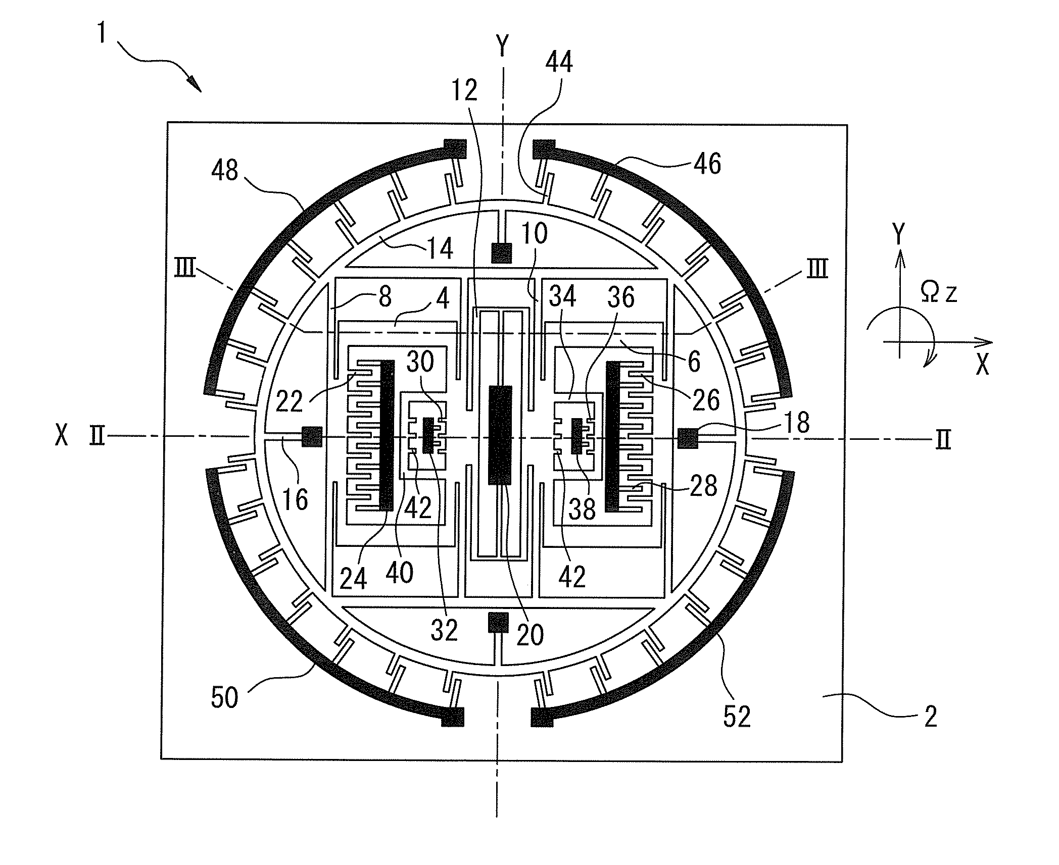
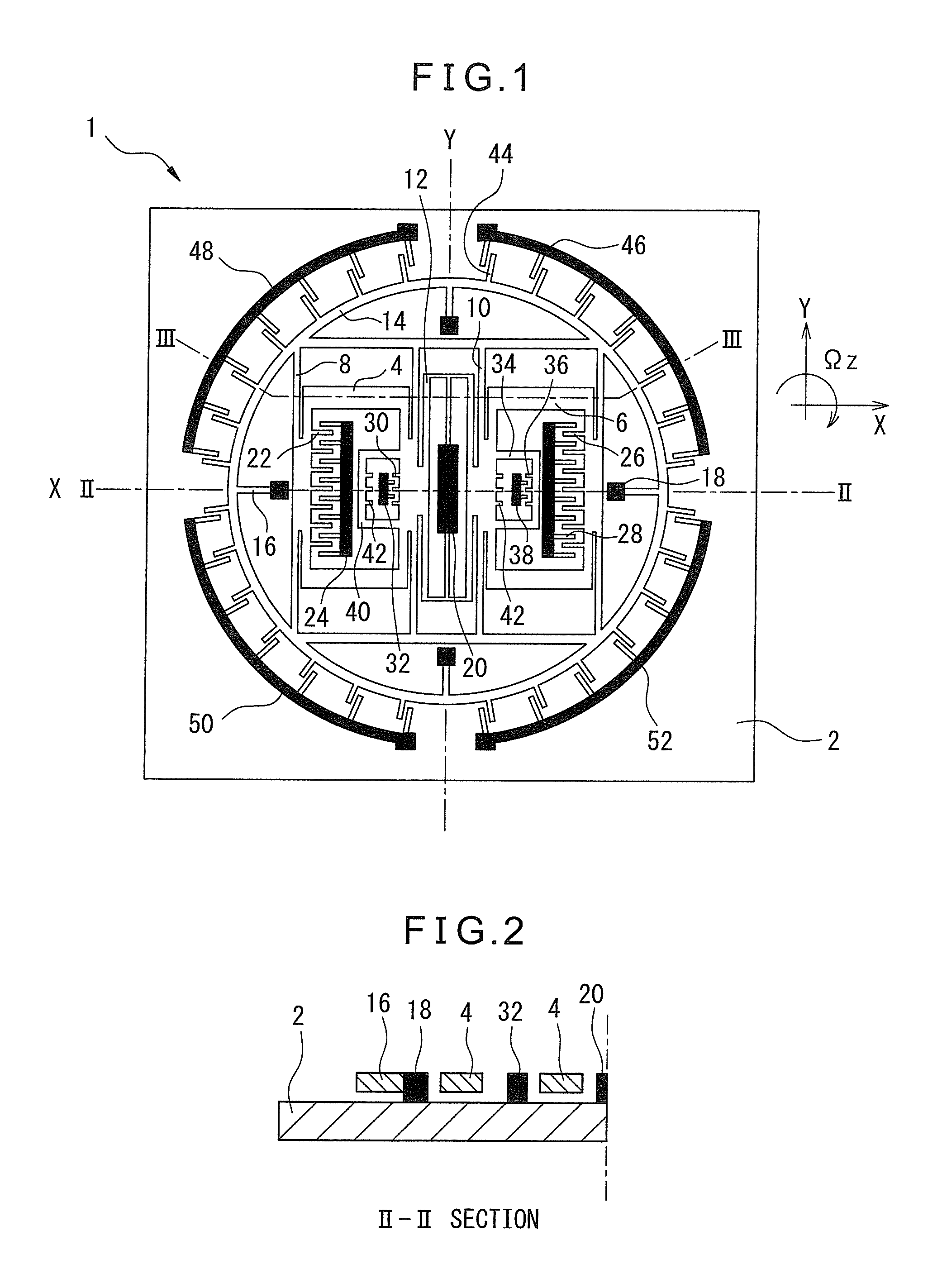
[0032]FIG. 1 is a plane view showing a basic configuration of a vibration gyro 1 according to the present invention, and FIGS. 2 and 3 are cross-sectional view along II-II and lines of FIG. 1, respectively.
[0033]In each drawing, reference numeral 2 represents a substrate constituted by an insulating material such as glass, and other structural components of vibration gyro 1 are made from monocrystalline silicon. In vibration gyro 1 of FIG. 1, drive masses 4 and 6, made from monocrystalline silicon, positioned on left and right sides (in this case, drive mass 4 is positioned on the left side) are supported by at least one (four in the embodiment) drive supporting element 8 and at least one (four in the embodiment) drive supporting element 10, respectively, the supporting elements extending in a Y-direction. Drive supporting elements 8 and 10 are configured so that the rigidity thereof in a drive direction (an X-direction) or a horizontal direction parallel to a surface of substrate 2...
second embodiment
[0082]In the above second embodiment, as the driving force for the left and right drive masses, the drive force in the X-direction generated between the drive comb electrode and the comb electrode arranged on the drive mass. Due to the structural unbalance caused by production tolerance, etc., (e.g., shape tolerance of the drive supporting element and / or the comb electrode), force in the Y-direction is applied to the left and right drive masses, and the force generates torque which causes rotational displacement (vibration) of the sense mass. As a result, the torque generated at each drive mass is not canceled each other, whereby the leakage output (or the quadrature error) may be generated by the rotational vibration.
[0083]In this regard, in the second embodiment as shown in FIGS. 8 and 9, correction fixed comb electrodes 151a and 151b are arranged so that the force in the −Y-direction is generated due to the DC voltage difference (V1−Vm) between correction fixed comb electrode 151...
third embodiment
[0099]In the third embodiment, when DC voltage is applied to left drive mass 204, the electrostatic force in the −Y-direction, corresponding to drive displacement X, is applied to left drive mass 204, whereby counterclockwise torque TCCW may be generated. Also, in the right drive mass, which is symmetrical to left drive mass 204 with respect to the Y-axis (B-B line) in FIG. 11, clockwise torque TCW may be generated when the same DC voltage is applied to the right drive mass. In other words, by appropriately adjusting the DC voltage applied to the correction fixed comb electrode arranged on each of the left and right drive masses, a correction torque (TCCW−TCW) for canceling the quadrature error (in the rotational direction of the sense mass) may be obtained. In addition, corresponding to the number of pairs of the combs opposed to each other (in the embodiment of FIG. 11, two pairs at each of the upper and lower fixed electrodes) the correction torque may be increased (i.e., when th...
PUM
 Abstract
Description
Claims
Application Information
 - R&D
- Intellectual Property
- Life Sciences
- Materials
- Tech Scout
- Unparalleled Data Quality
- Higher Quality Content
- 60% Fewer Hallucinations
Browse by: Latest US Patents, China's latest patents, Technical Efficacy Thesaurus, Application Domain, Technology Topic, Popular Technical Reports.
© 2025 PatSnap. All rights reserved.Legal|Privacy policy|Modern Slavery Act Transparency Statement|Sitemap|About US| Contact US: help@patsnap.com


