Steering wheel with finisher

Active Publication Date: 2013-11-14
NIHON PLAST CO LTD
View PDF2 Cites 1 Cited by
  • Summary
  • Abstract
  • Description
  • Claims
  • Application Information

AI Technical Summary

Benefits of technology

[0042]Moreover, a stress deforming the first and second finishers while twisting the first and second finishers is smaller than a stress required to deform both side surfaces of the U-shape in such a way that both side surfaces expand outward. Accordingly, the first and second finishers can be made to easily follow the direction of the deformation of the steering wheel without the fragile portions formed in the first and second finish

Problems solved by technology

However, the finisher is generally not configured to follow the deformation of the rim and the spokes even when the rim and the spokes deform.
Then, when the impact load acts on the steering wheel, bending deformation about the fragile portion occurs in the garnish.
An increase in cost and

Method used


Image

  • Steering wheel with finisher
  • Steering wheel with finisher
  • Steering wheel with finisher

Examples


Example

[0049]An embodiment of the present invention is specifically described below based on the attached drawings. Shapes and arrangement configurations which are different from the shape and arrangement configuration to be described below can be employed as the configuration of a steering wheel including finishers of the present invention as long as the shapes and arrangement configurations can solve the problems of the present invention. The present invention is thus not limited to the embodiment described below and various modifications can be made thereto.

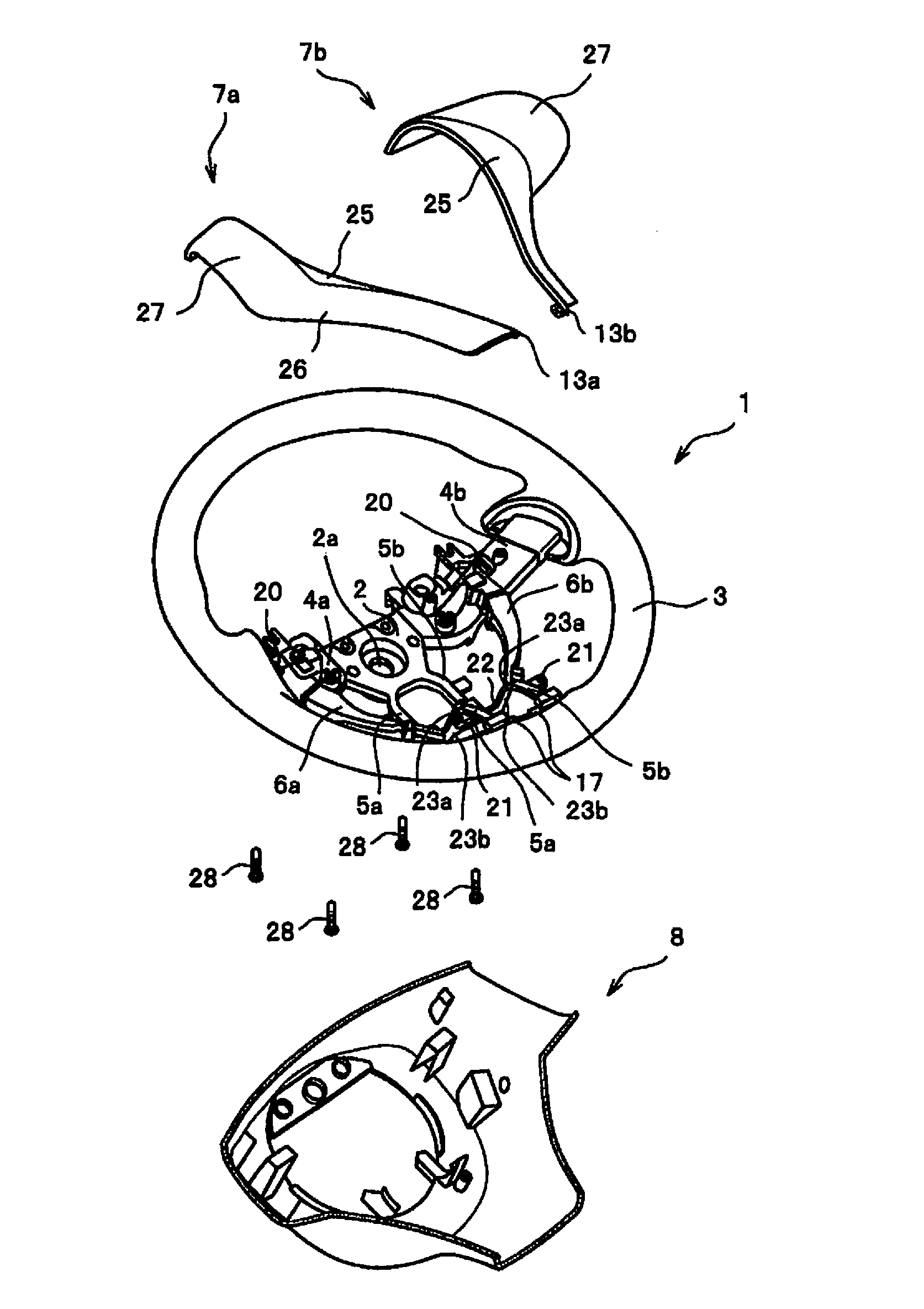
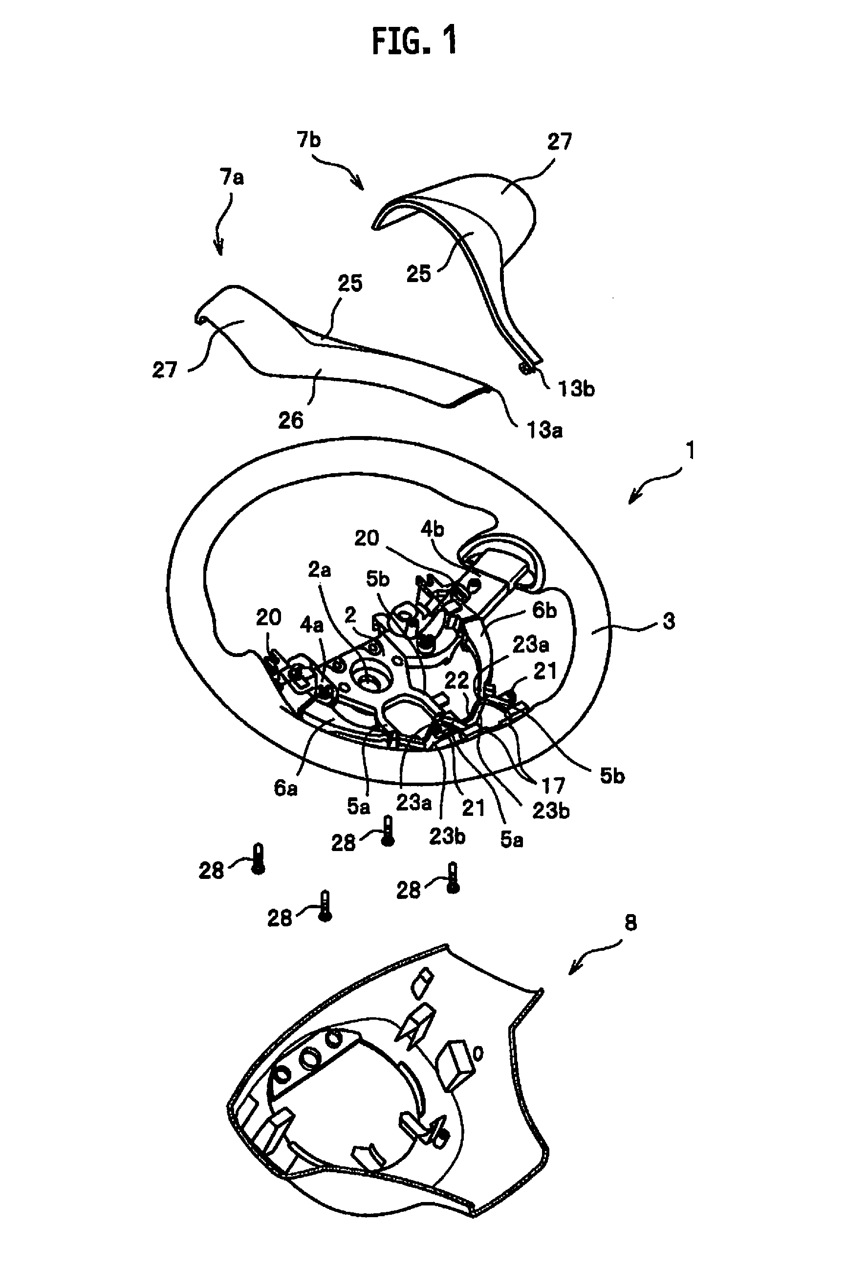
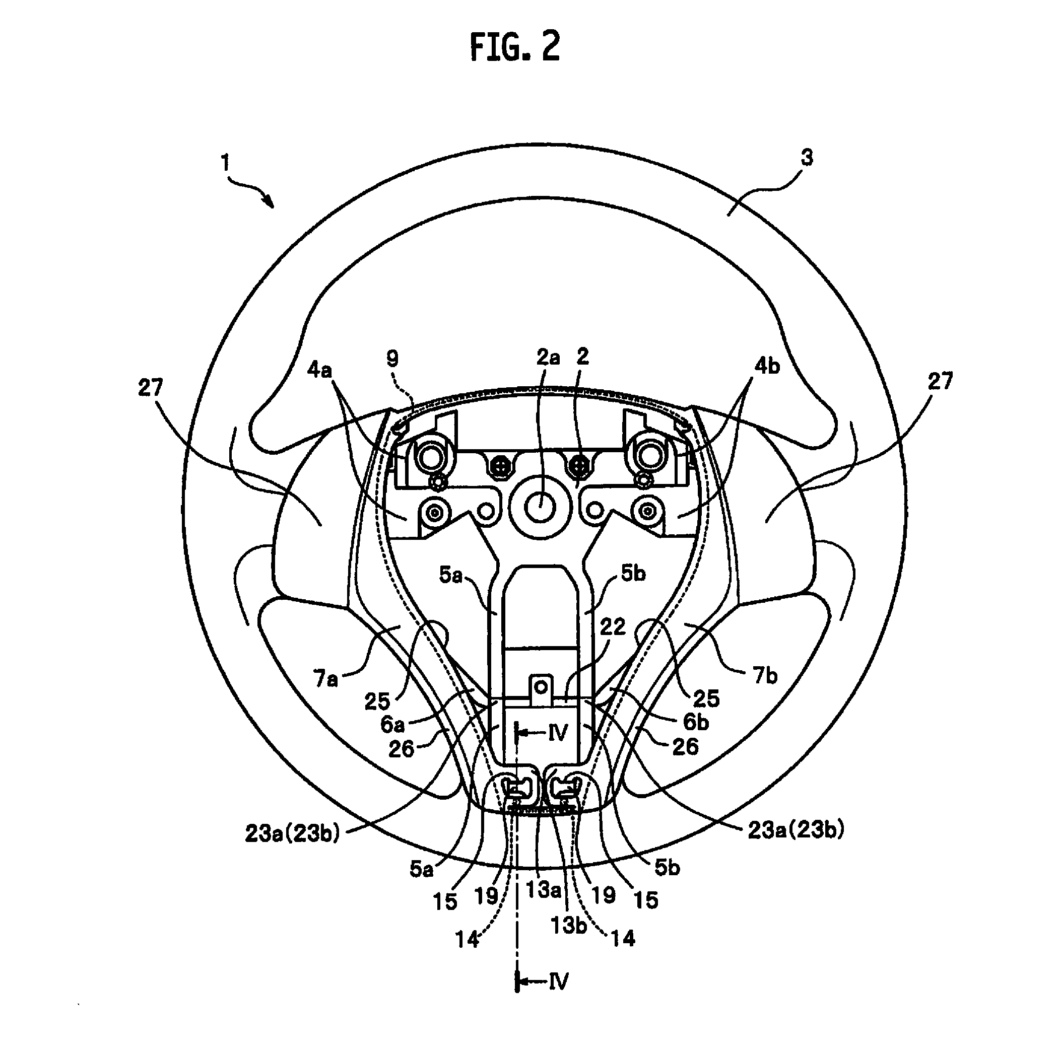
[0050]The embodiment of the present invention is described by using FIGS. 1 to 5. Note that, in the description, an up-down direction is defined such that a top end side and a bottom end side of a steering wheel 1 in a top view of the steering wheel 1 in a neutral state thereof are respectively an upper side and a lower side. Moreover, a direction intersecting the up-down direction is defined as a left-right direction. As shown in FI...


PUM


Abstract

In a lower end of a finisher having a substantially I-shape, an extending portion extending along a rim is provided. The finisher has an upper locking portion to be locked to an upper spoke and a lower locking portion provided in the extending portion and to be locked to a lower spoke. The lower locking portion has a protruding portion and a locking piece both standing upright from a back surface of the extending portion. The protruding portion and the locking piece are arranged away from each other in an up-down direction. The lower spoke has an engagement receiving portion for the protruding portion to be fitted and for the locking piece to be engaged.

Description

CROSS REFERENCE TO RELATED APPLICATION[0001]This application is based upon and claims the benefit of priority from the prior Japanese Patent Application No. 2012-110564, filed on May 14, 2012, the entire contents of which are incorporated herein by reference.BACKGROUND[0002]1. Technical Field[0003]The present invention relates to a steering wheel for steering a vehicle and particularly relates to a steering wheel with finisher.[0004]2. Related Art[0005]Recently, there are proposed various types of steering wheels employing deformable metal core structures to secure safety of drivers in vehicle crashes and the like. Such a steering wheel employs the following configuration: When an impact load is applied to, for example, the steering wheel in a vehicle crash or the like, a rim, which forms a turning outer periphery of the steering wheel, and spokes, which connect the rim and a boss, deform to an opposite side to a driver, thereby absorbing and alleviating the impact on the driver com...

Claims


Application Information

Patent Timeline
IPC IPC(8): B62D1/10
CPCB62D1/10B62D1/11Y10T74/20834B62D1/08
Inventor MURAMATSU, KATSUYA
Owner NIHON PLAST CO LTD
Why Eureka
Try Eureka