

Dust collection filter unit, projection image display device, and air cleaner
a technology of dust collection filter and projection image, which is applied in the direction of dispersed particle separation, instruments, separation processes, etc., can solve the problems of large amount of heat generation on the image, thermal destruction, brightness reduction or color unevenness, etc., to suppress the reduction in the function of the pleated filter, suppress the reduction of brightness and color unevenness, and high dust collection performance
- Summary
- Abstract
- Description
- Claims
- Application Information
AI Technical Summary
Benefits of technology
Problems solved by technology
Method used
Image

Examples
embodiment 1
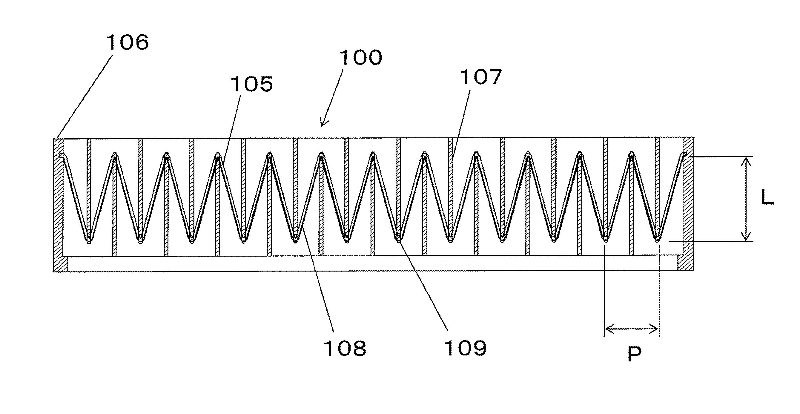
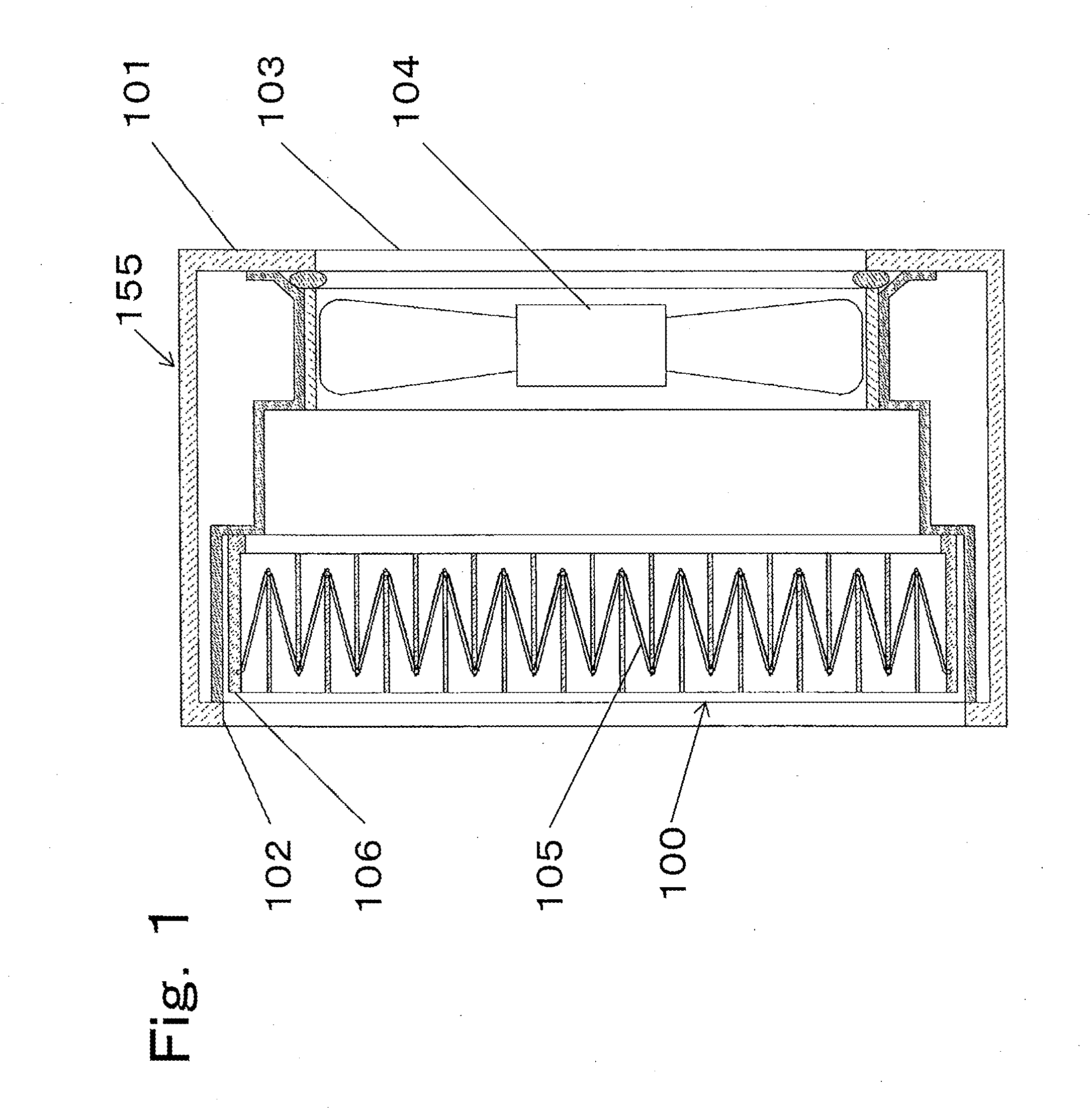
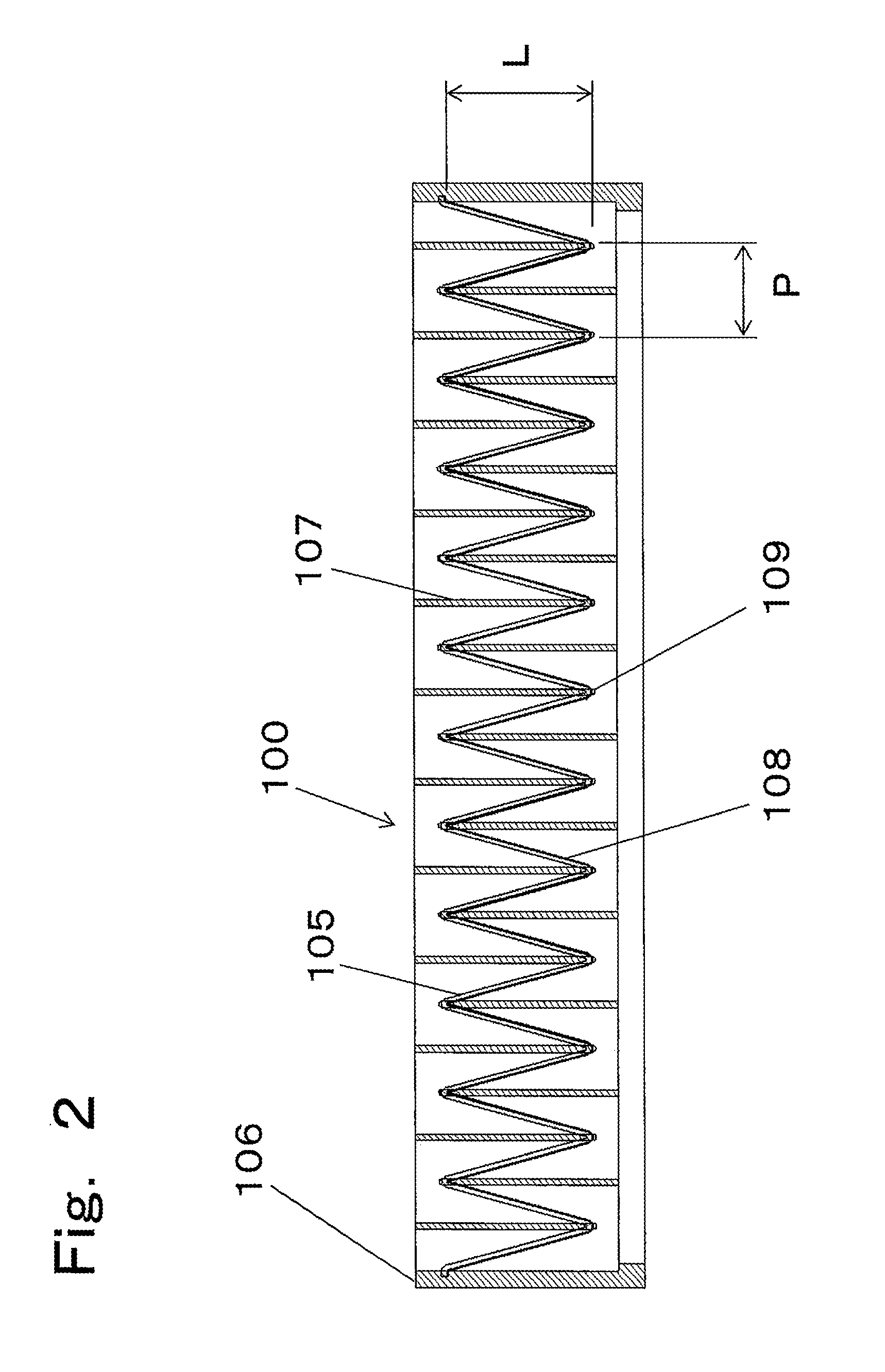
[0029]FIG. 1 is a sectional view of an air cleaner 155 according to embodiment 1 of the present invention, FIG. 2 is a sectional view of a dust collection filter unit 100 provided therein, and FIG. 3 is a perspective view of a filter frame 106, where an electrostatic filter 105 is omitted. A housing 101 has an air intake portion 102 and an air discharge portion 103. Inside the housing 101, an axial flow fan 104 driven by an external power supply, and the dust collection filter unit 100 placed on the air intake side with respect to the axial flow fan 104, are provided. The dust collection filter unit 100 has the electrostatic filter 105, and the filter frame 106 having a ventilation hole to which the electrostatic filter 105 is to be attached.
[0030]In the dust collection filter unit 100, the outer circumferential portion of the electrostatic filter 105 is embedded in the filter frame 106 by insert molding. In order to maintain the electrostatic filter 105 in a pleated shape (a foldin...
embodiment 2
[0047]FIG. 9 is a diagram showing the structure of the projection image display device 150 according to embodiment 2 of the present invention. The present invention does not relate to an optical configuration. Therefore, the optical configuration will be briefly described below.
[0048]In the projection image display device 150, light emitted from a light source 111 is caused to travel forward by a light reflection mirror 112, and then enters an optical unit 113. The light entering the optical unit 113 passes through dichroic mirrors 114 and 115 and total reflection mirrors 116, 117, and 118, thereby to be divided into color lights of red, green, and blue, and then the intensity of each light is modulated, in accordance with an input signal from outside (not shown), by entry side polarization plates 119R, 119G, and 119B, liquid crystal panels 120R, 120G, and 120B, and exit side polarization plates 121R, 121G, and 121B. These lights are synthesized onto one optical path by a synthesizi...
PUM
| Property | Measurement | Unit |
|---|---|---|
| Thickness | aaaaa | aaaaa |
| Volumetric flow rate per pressure | aaaaa | aaaaa |
| Shape | aaaaa | aaaaa |
Abstract
Description
Claims
Application Information