Holding table

a technology for holding tables and supports, which is applied in the field of holding tables, can solve the problems of support plates that cannot be held under suction on the holding table, support plates may be broken, and support plates may be flawed, so as to reduce the possibility of support plates flawing

Active Publication Date: 2013-11-14
DISCO CORP
View PDF16 Cites 8 Cited by
  • Summary
  • Abstract
  • Description
  • Claims
  • Application Information

AI Technical Summary

Benefits of technology

[0009]In the case that the platelike workpiece is a stacked workpiece formed by attaching a platelike workpiece to a support plate, only the outer circumferential portion of the support plate is held under suction on the annular holding member. Accordingly, it is possible to reduce the possibility of flawing of the support plate or adhesion of contaminants to the support plate, so that contamination of the transporting unit or the cassette can be prevented and the support plate can be reused.

Problems solved by technology

In the case that a stacked workpiece formed by attaching a workpiece to a support plate is held on the holding table under suction in the condition where the support plate comes into contact with the holding surface, the support plate may be flawed.
Even when the support plate thus flawed is reused, there is a possibility that the support plate cannot be held under suction on the holding table, depending on the size of flaws.
Further, when the workpiece attached to the support plate having flaws is subjected to processing with heat, there is a possibility that the support plate may be broken from the flaws and the workpiece may also be broken.
This is very uneconomical and the reuse of the support plate has been desired.

Method used


Image

  • Holding table
  • Holding table
  • Holding table

Examples


Embodiment Construction

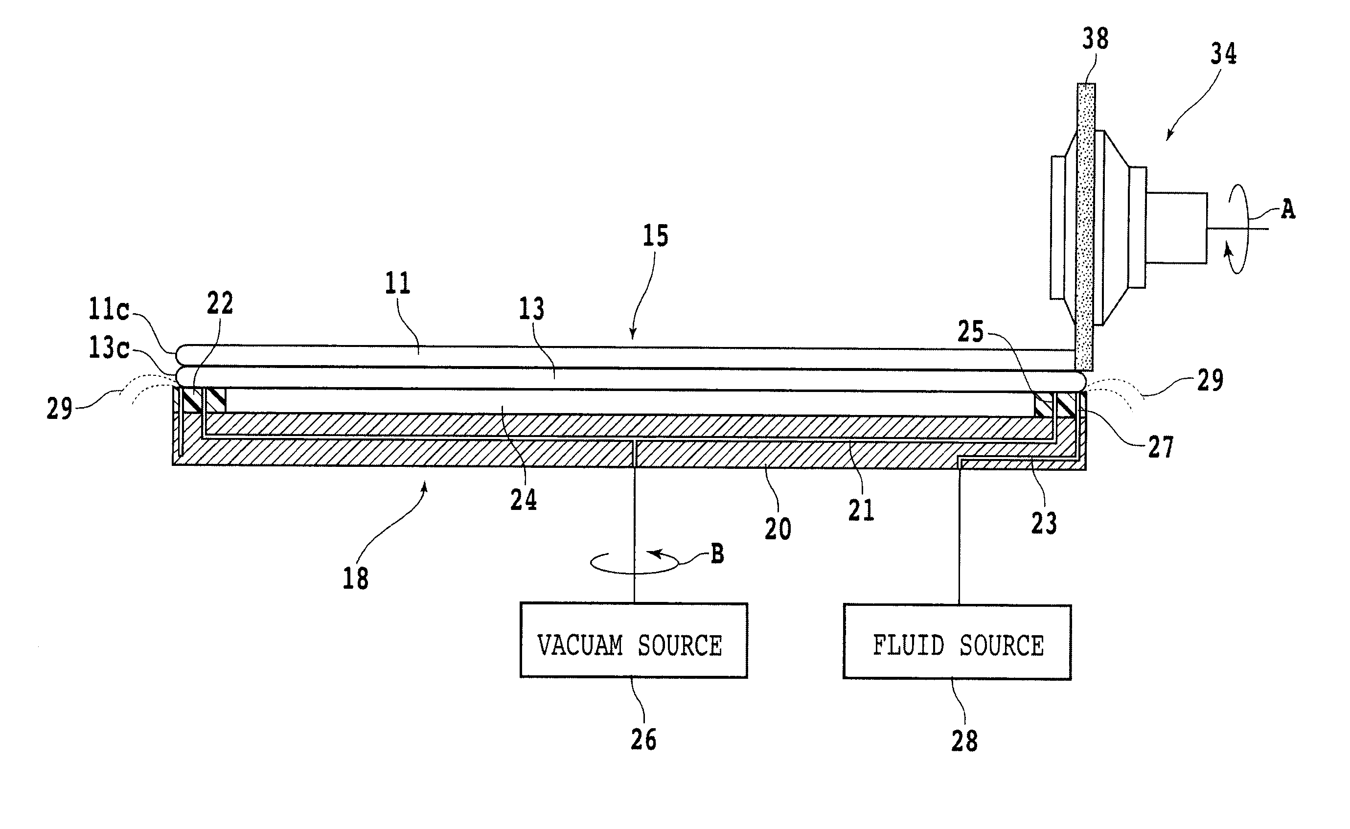
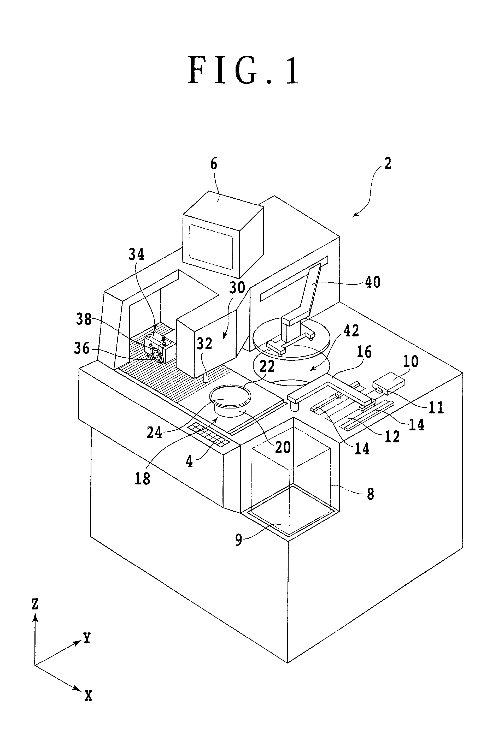
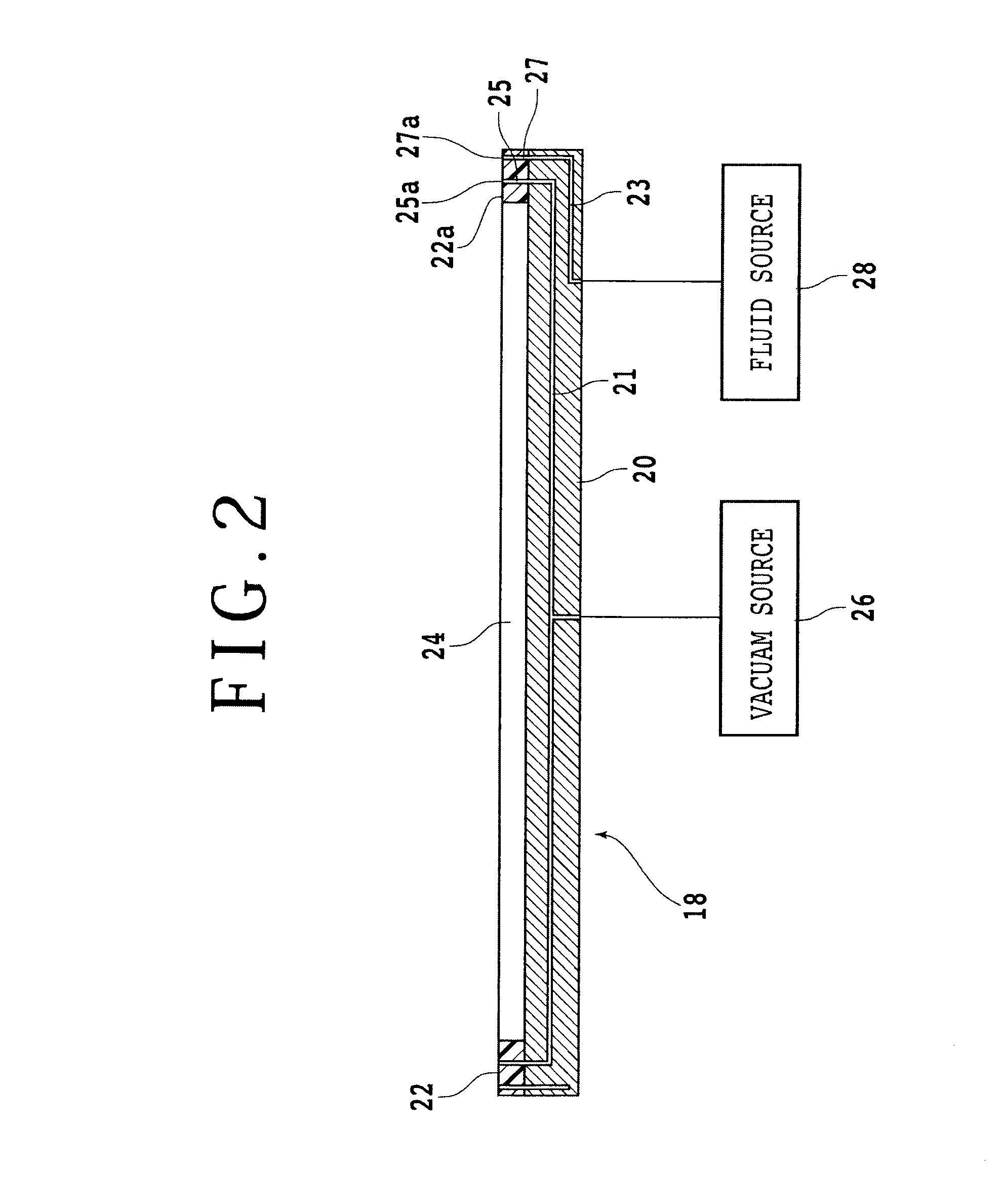
[0015]A preferred embodiment of the present invention will now be described in detail with reference to the drawings. Referring to FIG. 1, there is shown a perspective view of a cutting apparatus 2 including a holding table (chuck table) 18 according to a preferred embodiment of the present invention. The cutting apparatus 2 includes an operation panel 4 for allowing an operator to input instructions such as processing conditions to the apparatus 2. The operation panel 4 is provided at the front portion of the cutting apparatus 2. The cutting apparatus 2 further includes a display unit 6 such as a CRT for displaying a guide view to the operator or an image obtained by an imaging unit to be hereinafter described. The display unit 6 is provided at the upper portion of the cutting apparatus 2.

[0016]A plurality of (e.g., 25) platelike workpieces such as wafers are stored in a cassette 8. The cassette 8 is placed on a vertically movable cassette elevator 9. A handling unit 10 is provided...


PUM


Abstract

A holding table for holding a platelike workpiece which includes a base and an annular holding member attached to the base. The annular holding member has an annular holding surface for holding the outer circumferential portion of the platelike workpiece thereon. Accordingly, a central recess is defined by the base and the annular holding member so as to be surrounded by the annular holding member. The annular holding member is formed with a suction opening exposed to the annular holding surface, a vacuum line having one end communicating with the suction opening and the other end connected to a vacuum source, a discharge opening exposed to the annular holding surface at a position radially outside of the suction opening, and a fluid line having one end communicating with the discharge opening and the other end connected to a fluid source.

Description

BACKGROUND OF THE INVENTION[0001]1. Field of the Invention[0002]The present invention relates to a holding table for holding a platelike workpiece such as a wafer.[0003]2. Description of the Related Art[0004]A processing apparatus such as a grinding apparatus, cutting apparatus, and laser processing apparatus for processing a platelike workpiece such as a wafer includes a holding table (chuck table) having a holding surface for holding the platelike workpiece under suction as disclosed in Japanese Patent Laid-open No. Hei 5-23941 and Japanese Patent Laid-open No. 2008-140832, for example. In processing the workpiece held on the holding table under suction, there is a possibility that contaminants may adhere to the contact surface of the workpiece which comes into contact with the holding surface of the holding table.[0005]As a result, there is a possibility that the contaminants adhering to the workpiece may contaminate a transporting unit for transporting the workpiece or contamina...

Claims


Application Information

Patent Timeline
Patent Type & Authority Applications(United States)
IPC IPC(8): B23Q3/08
CPCB23Q3/088H01L21/304H01L21/67092H01L21/6838B23Q3/08H01L21/683B23Q1/38
Inventor KOMATSU, ATSUSHIKITAURA, TAKESHIKATAOKA, MASAMICHI
Owner DISCO CORP
Why Eureka
Try Eureka